LACP (Link Aggregation Control Protocol) is a standard protocol that combines multiple physical Ethernet connections into a single logical link and negotiates this aggregation between 2 devices. The protocol was first defined in IEEE 802.3ad and is now part of the IEEE 802.1AX standard. On Cisco devices, this structure is called EtherChannel, and the resulting logical interface is managed as a port-channel.
Running more than 1 cable between 2 switches does not increase bandwidth by itself. Spanning Tree Protocol treats the redundant links between the same 2 switches as a loop risk, leaves 1 of them in the Forwarding state and places the others in the Blocking state. Even if 4 cables are installed, a single cable carries the traffic and the remaining 3 stay idle until a failure occurs. Because LACP presents these physical links as a single logical connection, STP sees the port-channel as a single link. All active member links are ready to carry traffic. How the traffic is actually distributed across the members depends on the selected load-balancing method and on the hash results of the traffic flows.
This design has 2 concrete benefits. First, the logical bandwidth equals the total capacity of the member links. Second, when 1 of the member links fails, traffic continues over the remaining links and the STP topology does not change. For this reason, LACP is a configuration found at almost every layer of enterprise networks, from the uplinks between the access and distribution layers to server and storage connections.
The article is based on the EtherChannel topic in the Cisco CCNA curriculum, and it follows the behaviour of the Catalyst 9300 series and IOS-XE so that it can be used as a direct reference in the field. The first scenario builds a 20G port-channel on 10G uplink ports and then raises the capacity to 40G by adding new ports to the bundle. The second scenario applies the same logic to 1G access ports and creates a second port-channel with 4G capacity.
How LACP and EtherChannel Work
Before the configuration, it is necessary to clarify how LACP forms the bundle between 2 switches and under which conditions it accepts a port into the bundle. Most port-channel problems seen in the field are caused by a mode mismatch or by configuration differences between the member ports.
LACP Modes
LACP communicates with the other side through control packets called LACPDUs (LACP Data Units). These packets tell the other side which bundle the port belongs to, the system priority and the port state. The mode specified in the channel-group command determines whether the port sends LACPDUs. PAgP (Port Aggregation Protocol), which Cisco developed itself, uses the desirable and auto modes. LACP is a standard protocol, so it also works between devices from different vendors.
The mode combination used at the 2 ends directly determines whether the port-channel forms. The table below shows the possible combinations and the result of each.
|
SW1 Mode |
SW2 Mode |
Result |
|
active |
active |
The port-channel forms. Both sides start the negotiation by sending LACPDUs. |
|
active |
passive |
The port-channel forms. The side in active mode starts the negotiation. |
|
passive |
passive |
The port-channel does not form. Both sides wait for an LACPDU from the other side. |
|
on |
on |
The port-channel forms statically without LACP. No negotiation takes place. |
|
on |
active or passive |
The port-channel does not form. The on mode does not send LACPDUs and does not process received LACPDUs. |
In both scenarios, both ends are configured in active mode. Because the on mode does not negotiate, it cannot detect incorrect cabling or a configuration error on the other side, and it creates a risk of a Layer 2 loop. This is why active mode is preferred for LACP in the field.
An LACP port-channel can contain a maximum of 16 ports. Of these, 8 carry traffic actively, and the remaining 8 wait in the hot-standby state and take the place of an active member when it fails.
Member Port Compatibility Requirements
When an EtherChannel is created, the speed and duplex values, the Layer 2 mode and the VLAN and trunk parameters of the member ports in the same channel group must be compatible on each switch. Cisco IOS-XE can leave an incompatible member port out of the EtherChannel or place it in the suspended state.
The physical port numbers and the port-channel numbers do not have to be the same on the 2 switches. However, the VLAN and trunk configuration between the ends must be planned consistently so that the intended traffic works correctly. The table below lists the parameters that must be compatible between the member ports of the same channel group on each switch.
|
Parameter |
Requirement |
|
Speed and Duplex |
All member ports must operate at the same speed and duplex setting. 1G and 10G ports cannot be combined in the same port-channel. |
|
Switchport Mode |
All member ports must be in trunk mode, or all must be in access mode. |
|
Allowed VLAN |
On trunk ports, the allowed VLAN list must be the same on all members. |
|
Native VLAN |
On trunk ports, the native VLAN must be the same on all members and must be planned consistently with the native VLAN on the other side. |
|
Access VLAN |
On ports in access mode, the assigned VLAN must be the same on all members. |
After the port-channel is formed, VLAN and trunk changes must be made on the port-channel interface, not on the member ports. A setting applied to the port-channel is passed on to the member ports.
LACP Configuration on Uplink Ports
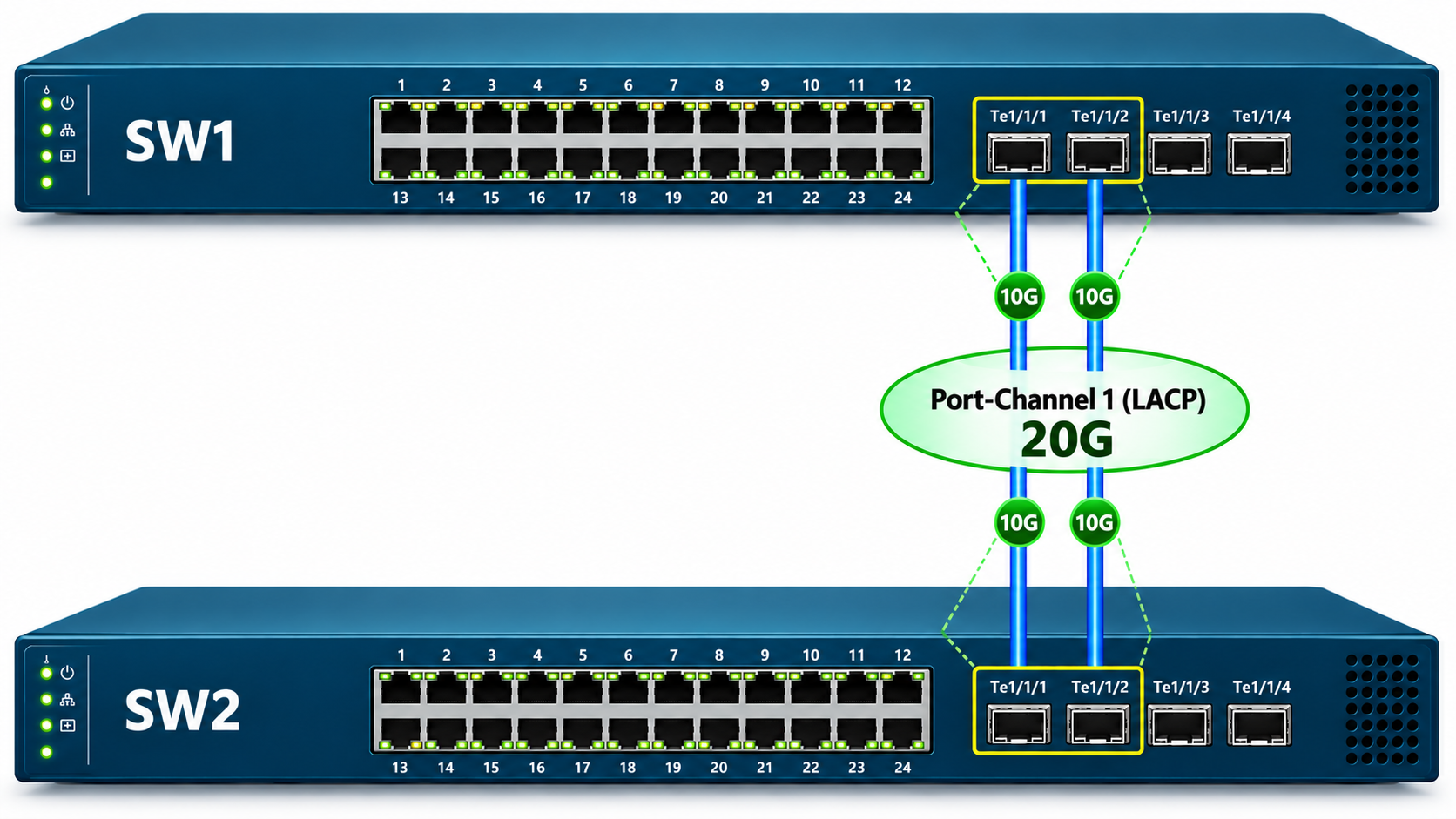
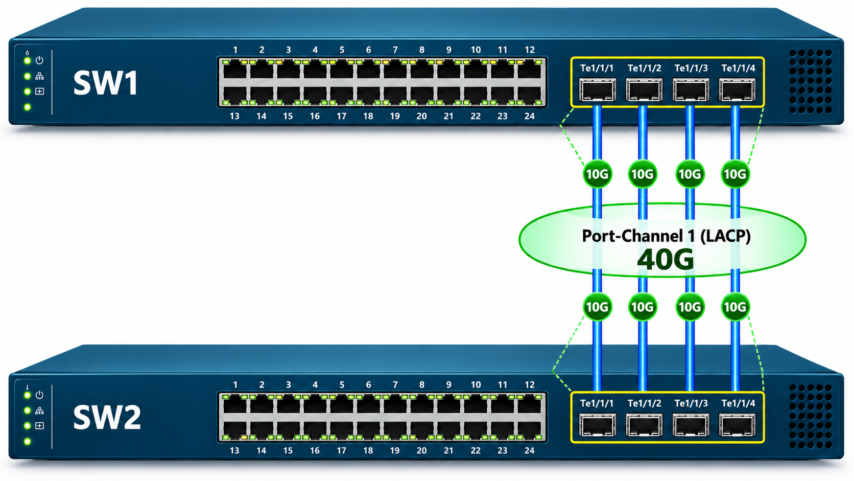
In the first scenario, 2 Catalyst 9300 switches connect to each other through the ports on the 10G SFP+ uplink module. The configuration has 2 stages. First, a 20G port-channel is built with 2 ports. Then 2 more ports are added to the existing bundle and the capacity rises to 40G. This sequence also shows how an existing port-channel is expanded without being deleted when more capacity is needed.
Topology and Port Layout
SW1 and SW2 connect to each other with 2 separate 10G links through ports Te1/1/1 and Te1/1/2 on the uplink module. The abbreviation Te stands for TenGigabitEthernet ports, which operate at 10 Gbps. The notation 1/1/1 gives the stack member number, the module number and the port number, in that order. When these 2 links are combined under Port-Channel 1, they form a single 20G logical connection between the 2 switches.
Port-Channel Configuration on SW1
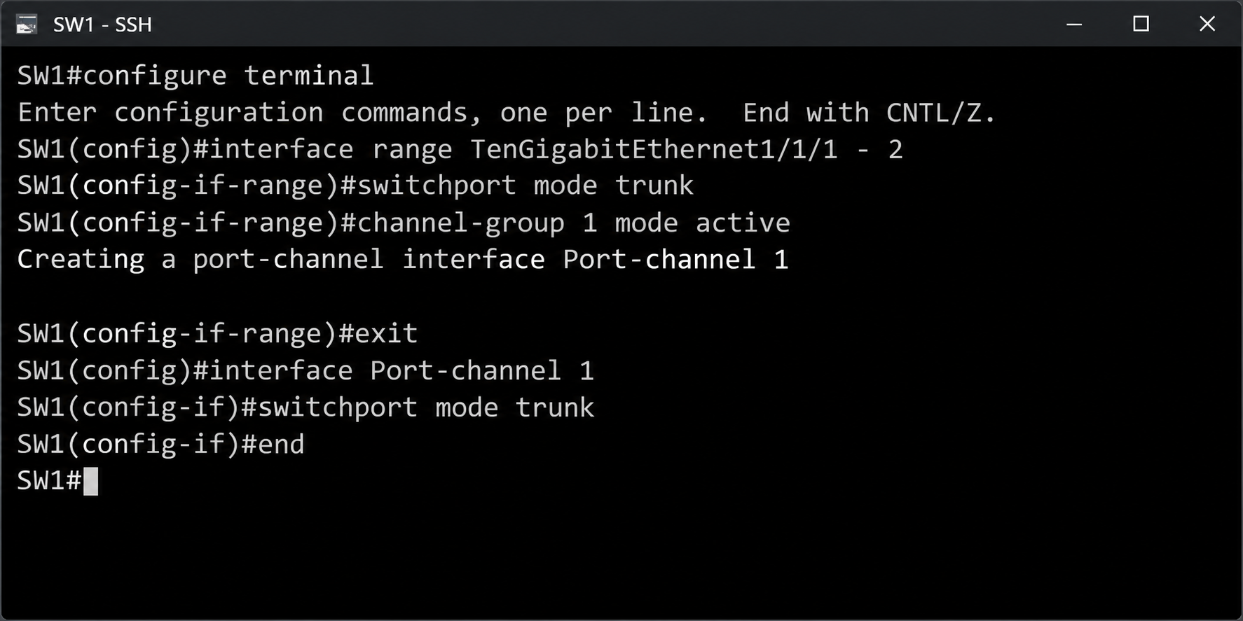
The configuration starts by selecting the 2 ports together with the interface range command. The ports are first set to trunk mode and then made members of Port-Channel 1 with the channel-group 1 mode active command. The Catalyst 9300 supports only 802.1Q encapsulation on trunk ports, so the switchport trunk encapsulation command is not needed.
configure terminal
interface range TenGigabitEthernet1/1/1 - 2
switchport mode trunk
channel-group 1 mode active
exit
interface Port-channel 1
switchport mode trunk
end
As soon as the channel-group command is entered, the switch creates a logical interface named Port-channel 1 and reports this with the message Creating a port-channel interface Port-channel 1. Defining trunk mode separately on the port-channel interface ensures that the logical interface and the member ports carry the same Layer 2 configuration.
Port-Channel Configuration on SW2
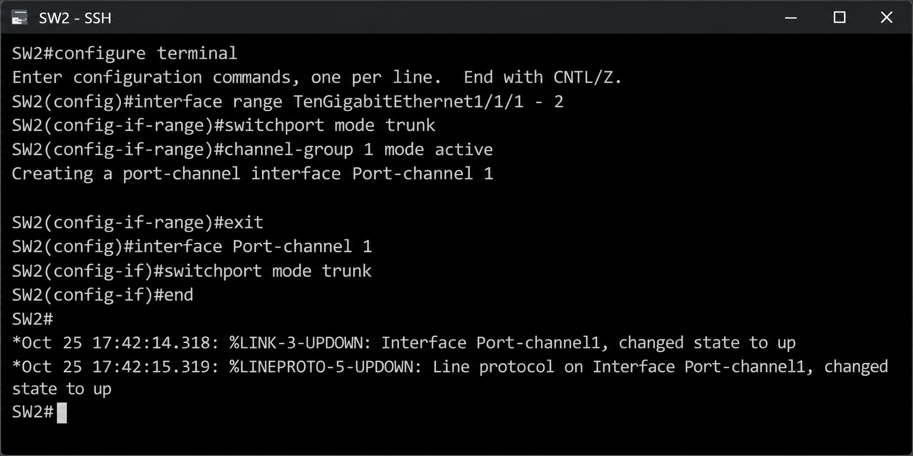
The same configuration is applied on SW2. Because both ends are in active mode, both switches start the negotiation by sending LACPDUs.
configure terminal
interface range TenGigabitEthernet1/1/1 - 2
switchport mode trunk
channel-group 1 mode active
exit
interface Port-channel 1
switchport mode trunk
end
When the negotiation is complete, the %LINK-3-UPDOWN and %LINEPROTO-5-UPDOWN syslog messages show that the Port-channel1 interface changes to the up state first at the physical level and then at the line protocol level. These 2 messages are the first indication that the LACP negotiation has completed successfully. The members that the port-channel runs with are checked with the verification commands.
Verifying the Port-Channel Status
The fastest way to see the status of the port-channel and its member ports is the show etherchannel summary command. To see the bandwidth and the member list, the output of show interfaces Port-channel 1 is narrowed with the include filter.
show etherchannel summary
show interfaces Port-channel 1 | include BW|Members
The Po1(SU) entry in the output shows that the port-channel operates at Layer 2 and is in use. The LACP value in the Protocol column shows that the bundle was built with LACP, and the P flag in Te1/1/1(P) and Te1/1/2(P) shows that both ports are in the bundle. The BW value of 20000000 Kbit/sec confirms that the port-channel runs at 20 Gbps.
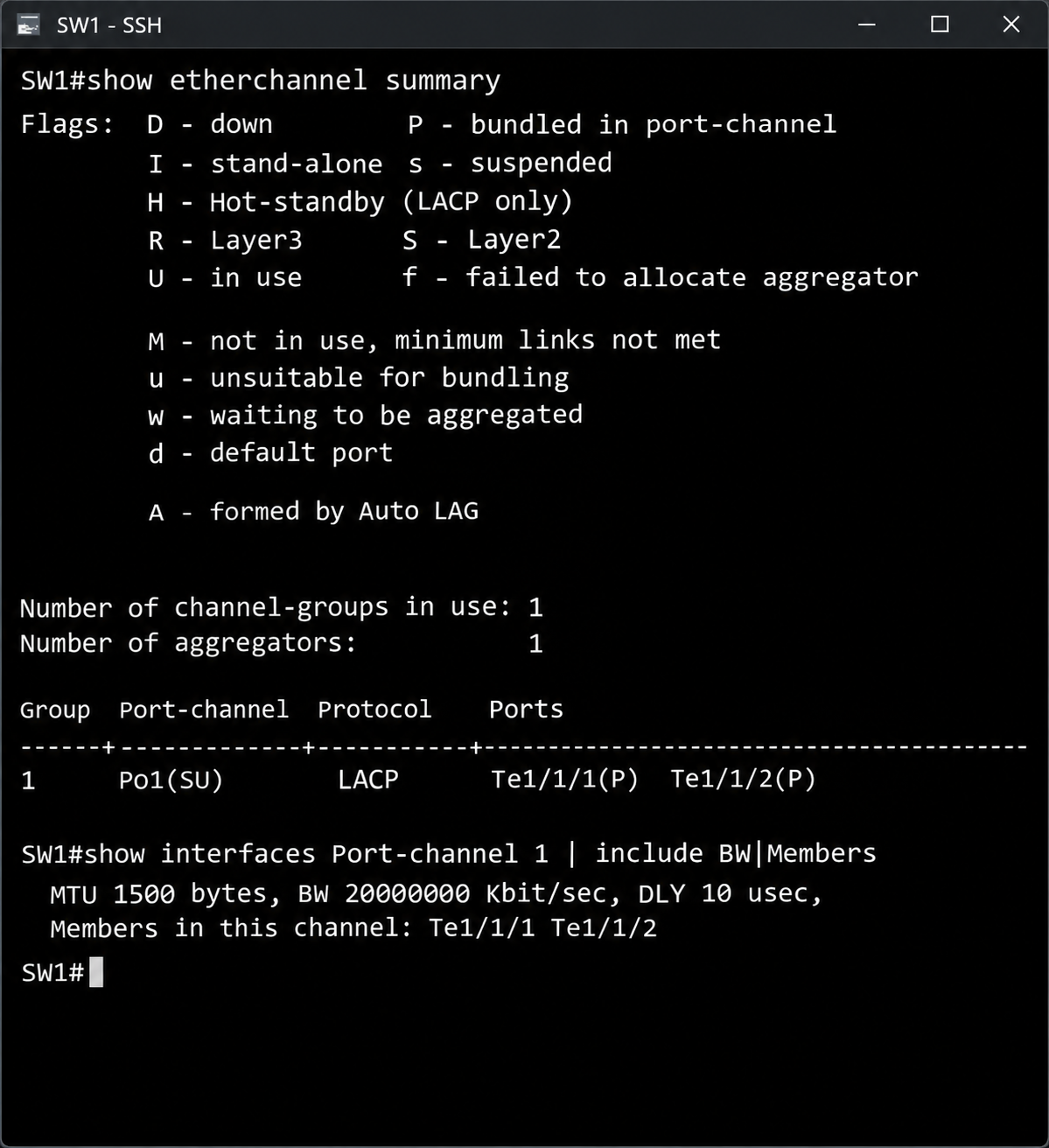
The flags at the top of the output are used during troubleshooting to understand why a port was not included in the bundle. The table below lists the flags seen most often in the field and their meanings.
|
Flag |
Text in the Output |
Meaning |
|
P |
bundled in port-channel |
The port is in the bundle and carries traffic. |
|
s |
suspended |
The port was left out of the bundle because of a configuration mismatch. |
|
I |
stand-alone |
No LACPDU was received from the other side, and the port operates independently. |
|
H |
Hot-standby |
The port waits on standby because the active member limit is reached. |
|
D |
down |
The port is physically down. |
|
S |
Layer2 |
The port-channel operates at Layer 2. |
|
U |
in use |
The port-channel is in use. |
Adding New Member Ports to the Port-Channel
When more capacity is needed, there is no need to delete the existing port-channel. New ports are added to the existing bundle with the same channel-group number. In this step, ports Te1/1/3 and Te1/1/4 are also added to Port-Channel 1, which gives 40G capacity with 4 links of 10G each.
configure terminal
interface range TenGigabitEthernet1/1/3 - 4
switchport mode trunk
channel-group 1 mode active
end
Port-Channel 1 already exists, so the Creating message is not displayed this time. The same commands must also be applied on SW2. Until the other side is configured, the new ports do not receive LACPDUs and therefore do not join the bundle.
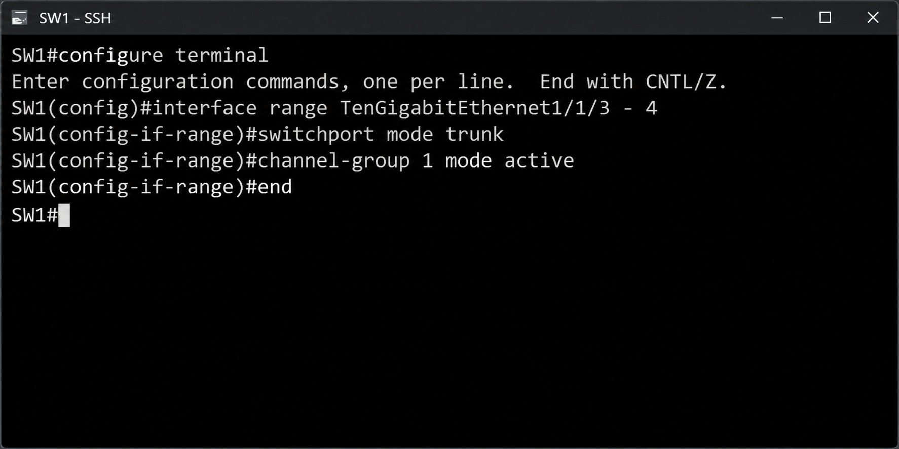
The speed, switchport mode and VLAN settings of the new ports must be compatible with the existing members. Otherwise, the port is not accepted into the bundle and can go into the suspended state.
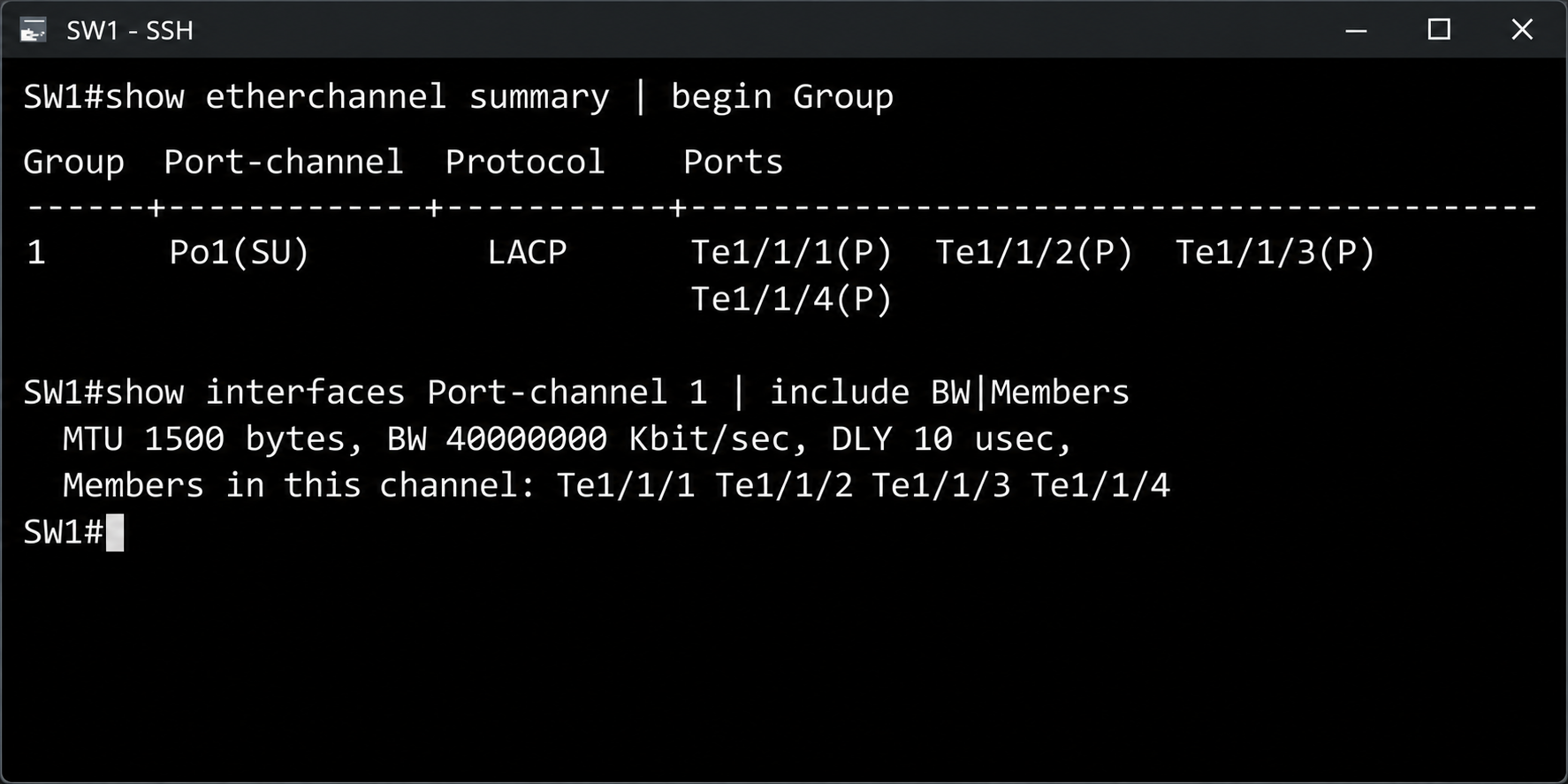
After the configuration is complete on both sides, the verification commands are run again. This time, the begin Group filter starts the show etherchannel summary output directly at the port-channel table.
show etherchannel summary | begin Group
show interfaces Port-channel 1 | include BW|Members
All 4 ports are in the bundle with the P flag. The BW value is updated to 40000000 Kbit/sec, and the Members line lists 4 member ports. The port-channel now runs with a logical capacity of 40 Gbps.
Load-Balancing Method and Actual Bandwidth
A port-channel with 40G capacity does not mean that a single connection reaches 40 Gbps. EtherChannel distributes traffic per flow, not per packet. For each frame, the switch calculates a hash value from the fields defined by the load-balancing method and uses this value to decide which member link sends the frame. Traffic that belongs to the same flow produces the same hash result, so it always uses the same member link. This approach prevents packets from arriving out of order.
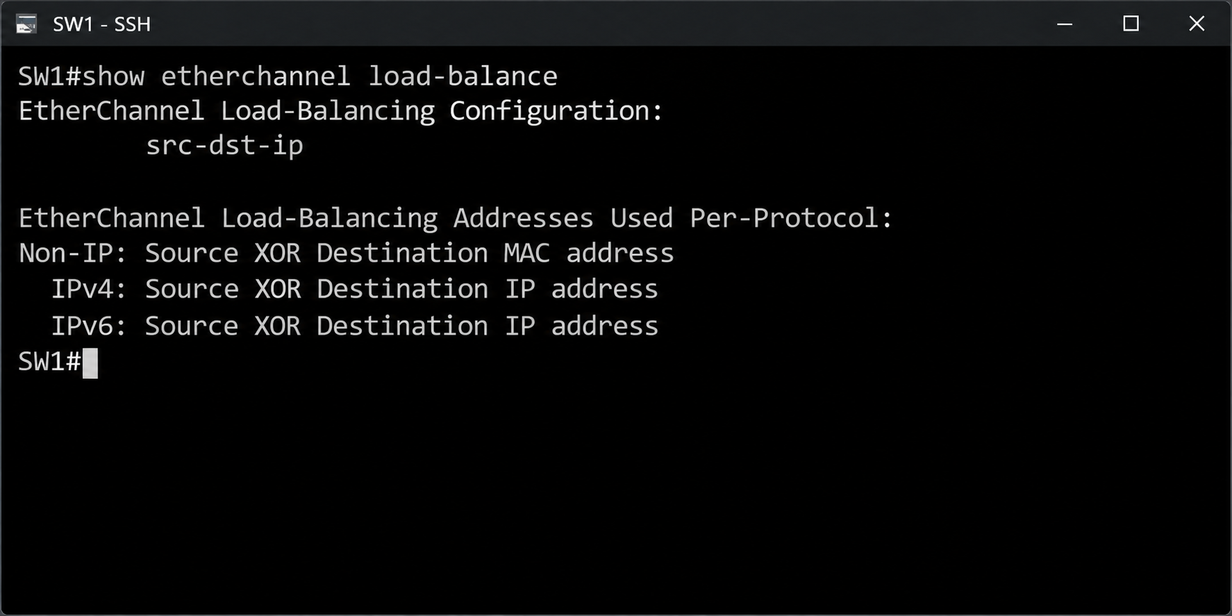
For this reason, a single flow is limited to the speed of 1 member link. This limit is 10 Gbps in the uplink scenario and 1 Gbps in the access port scenario. How the traffic between a client and a server is distributed across the members depends on the method in use. With a method that uses the source and destination IP addresses, such as src-dst-ip, all traffic between the same client and server goes to the same member link. With a method that also includes the Layer 4 port numbers in the hash calculation, such as src-dst-mixed-ip-port, different TCP and UDP sessions between the same 2 IP addresses can be distributed to different member links. The total capacity of the port-channel is reached only when a large number of different flows are distributed across the member links. The show etherchannel load-balance command shows which fields the switch uses in the hash calculation.
show etherchannel load-balance
The src-dst-ip value in the output shows the load-balancing method used on this switch. For IPv4 and IPv6 traffic, the hash value is produced by an XOR operation on the source and destination IP addresses. For non-IP traffic, the source and destination MAC addresses are used.
If the traffic pattern is not distributed evenly with the current method, the method can be changed with the port-channel load-balance command in global configuration mode. For an even hash distribution, Cisco recommends planning the number of port-channel members as 2, 4 or 8. The table below lists the commonly used methods and the scenarios they suit.
|
Method |
Fields Used in the Hash Calculation |
Suitable Scenario |
|
src-mac |
Source MAC address |
Layer 2 designs where many clients send traffic to the same gateway |
|
src-dst-mac |
Source and destination MAC addresses |
Layer 2 environments with a high volume of non-IP traffic |
|
src-dst-ip |
Source and destination IP addresses |
General-purpose enterprise networks |
|
src-dst-mixed-ip-port |
Source and destination IP addresses and Layer 4 port numbers |
Server and storage connections where many sessions are opened between the same 2 IP addresses |
configure terminal
port-channel load-balance src-dst-mixed-ip-port
end
port-channel load-balance is a global setting and affects all port-channels on the switch. The setting determines how outgoing traffic is distributed, so each switch is configured separately on its own side.
LACP Configuration on Access Ports
In the second scenario, a second port-channel is built between the same 2 switches, this time with the 1G copper ports on the front panel. This design is a method often used in the field to provide capacity and redundancy between switches whose uplink ports are full or that have no 10G module.
The term access port here describes the user ports on the front panel of the switch and must not be confused with the access mode in the VLAN configuration. The port-channel built from these ports carries more than 1 VLAN between the 2 switches, so it is configured in trunk mode, as in the uplink scenario.
Topology and Port Mapping
SW1 uses ports Gi1/0/13 to Gi1/0/16 in the bottom row, and SW2 uses ports Gi1/0/1 to Gi1/0/4 in the top row. The abbreviation Gi stands for GigabitEthernet ports, which operate at 1 Gbps. The 4 links of 1G each are combined under Port-Channel 2 and form a logical connection with 4G capacity.
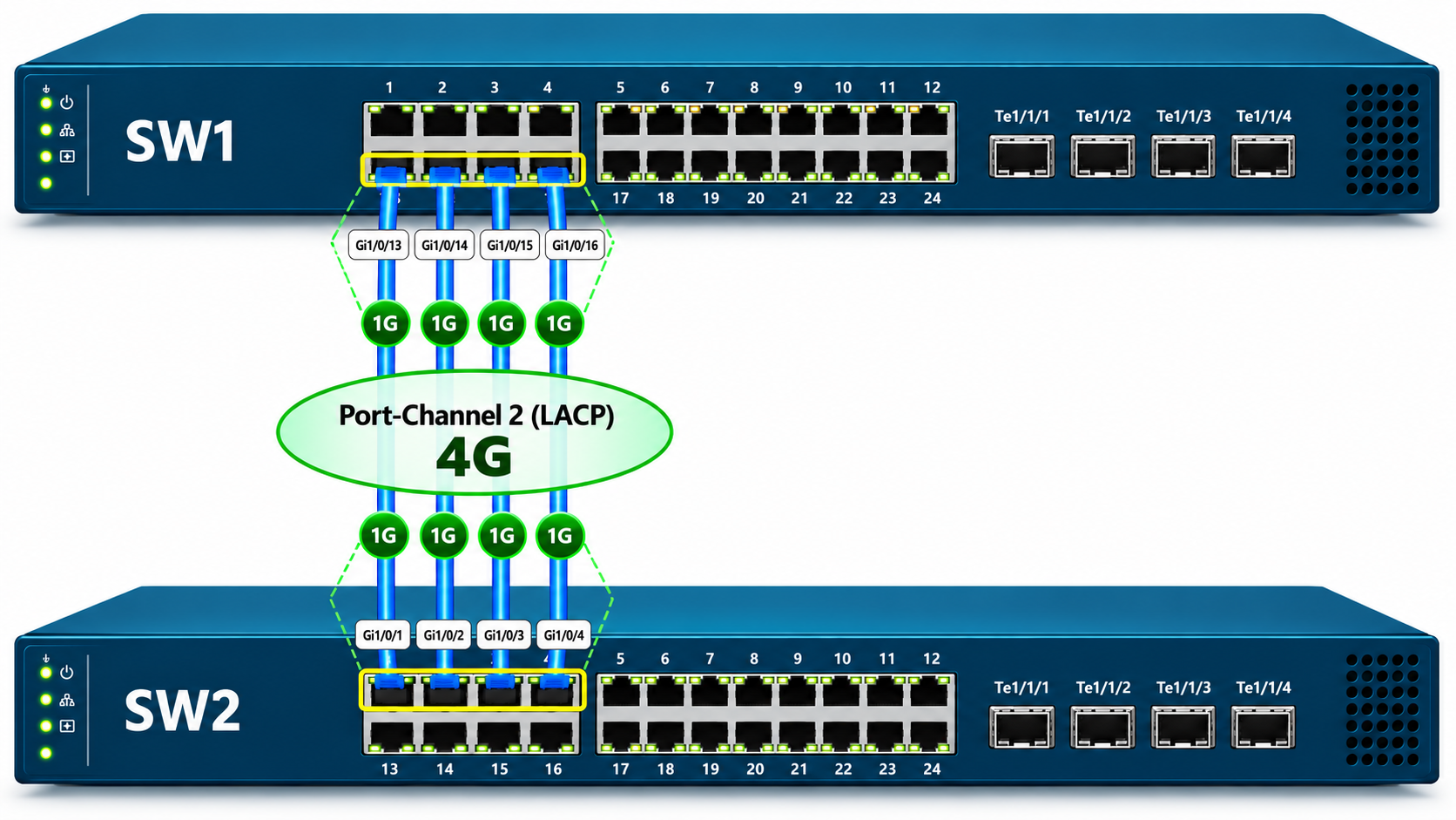
Using different port numbers at the 2 ends does not cause a problem for LACP. The member port numbers and the port-channel numbers at the 2 ends of the port-channel do not have to match. What must be compatible is the speed and the Layer 2 configuration of the member ports on each switch. The table below shows the port mapping used in the cabling.
|
Link |
SW1 Port |
SW2 Port |
Speed |
|
1 |
Gi1/0/13 |
Gi1/0/1 |
1 Gbps |
|
2 |
Gi1/0/14 |
Gi1/0/2 |
1 Gbps |
|
3 |
Gi1/0/15 |
Gi1/0/3 |
1 Gbps |
|
4 |
Gi1/0/16 |
Gi1/0/4 |
1 Gbps |
Port-Channel Configuration on SW1
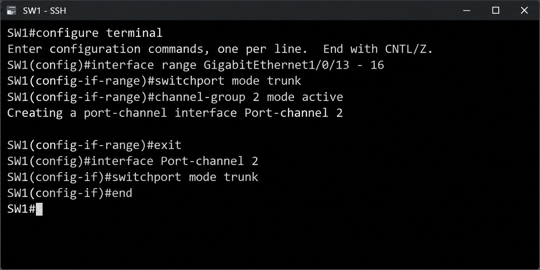
The configuration logic is the same as in the uplink scenario. The differences are that the interface type is GigabitEthernet and that the port-channel number is 2. Port-Channel 1 is used by the uplink ports, so the access ports are grouped under a separate channel-group.
configure terminal
interface range GigabitEthernet1/0/13 - 16
switchport mode trunk
channel-group 2 mode active
exit
interface Port-channel 2
switchport mode trunk
end
The channel-group 2 command creates the Port-channel 2 interface, and trunk mode is then defined on the port-channel.
Port-Channel Configuration on SW2
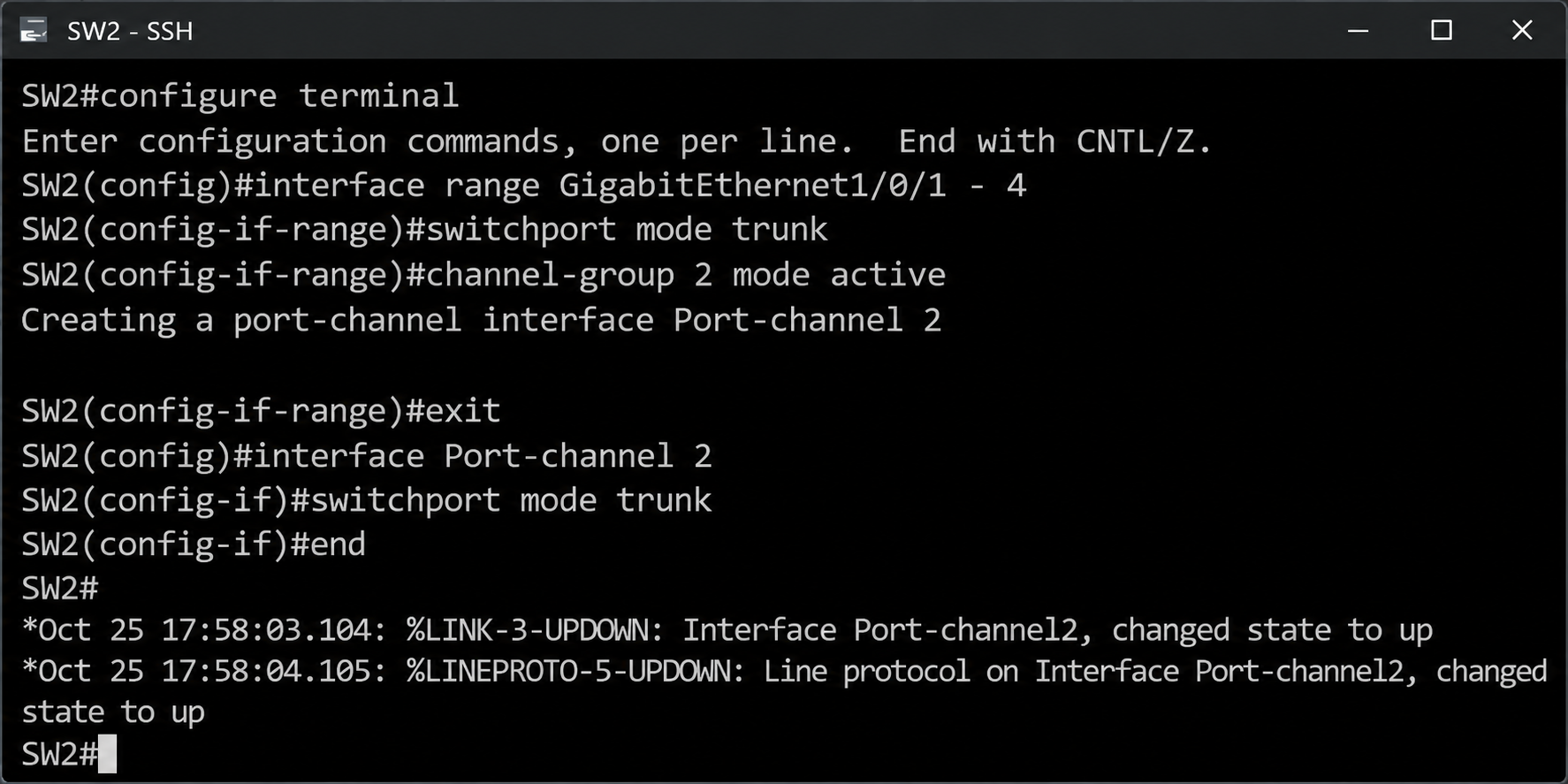
On SW2, the same command set is applied to ports Gi1/0/1 to Gi1/0/4.
configure terminal
interface range GigabitEthernet1/0/1 - 4
switchport mode trunk
channel-group 2 mode active
exit
interface Port-channel 2
switchport mode trunk
end
The %LINK-3-UPDOWN and %LINEPROTO-5-UPDOWN messages for Port-channel2 show that the LACP negotiation between the 2 switches is complete and that the port-channel has changed to the up state.
Verifying the Port-Channel Status
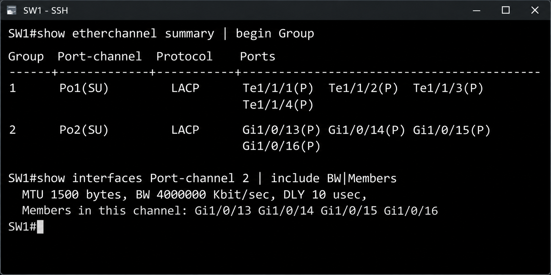
For verification, the commands from the uplink scenario are run for Port-channel 2.
show etherchannel summary | begin Group
show interfaces Port-channel 2 | include BW|Members
The output shows both port-channels together. Po1 runs with 4 members at 10G and Po2 runs with 4 members at 1G, both in the SU state, and all member ports have the P flag. The BW value of 4000000 Kbit/sec for Port-channel 2 confirms that the bundle built from the access ports runs at 4 Gbps. Flow-based distribution also applies here, and a single flow is limited to 1 Gbps.
In an LACP configuration, the deciding factor is not the port type but the compatibility of the member ports with each other. The same command set and the same verification steps are used on 10G uplink ports and on 1G access ports. Choosing active mode at both ends, managing member port settings through the port-channel interface and including the single-flow limit in capacity planning prevent most of the problems that would otherwise appear later in the field.
This article covered EtherChannel configuration with LACP on Cisco Catalyst 9300 switches through 2 different scenarios, 10G uplink ports and 1G access ports. It showed in practice how LACP combines multiple physical links under a single logical port-channel, how this prevents Spanning Tree Protocol from placing the redundant links in the Blocking state, and how it increases bandwidth.
In a port-channel configuration, the active and passive modes, the LACPDU negotiation and the speed, duplex, trunk and VLAN compatibility between the member ports on each switch are the deciding factors. The flags in the show etherchannel summary output are the first place to check in the field to understand why a port was not included in the bundle.
Because of the flow-based load-balancing mechanism, the total capacity that EtherChannel provides is limited to the member link speed for a single flow. When the hash method is selected according to the traffic pattern and the number of members is planned as 2, 4 or 8, the port-channel capacity is used more evenly.
LACP, which is part of the Cisco CCNA curriculum, is used across a wide area of enterprise networks, from uplinks between switches to server connections, and it brings redundancy and capacity together in the same configuration.
I hope you find it useful...
Feel free to share your thoughts and questions about this article in the comments below. Every contribution helps the content reach more people and makes for a more useful discussion.