A VLAN (Virtual Local Area Network) is a Layer 2 technology that divides a single physical switch infrastructure into logical networks that are independent of each other. I define on the switch which port belongs to which logical network, without touching the cabling. If 2 computers connected to the same switch are in different VLANs, they do not see each other at Layer 2. If 2 computers connected to different switches are in the same VLAN, they communicate as if they were connected to the same switch.
To understand why VLANs are needed, it is necessary to look first at how a switch forwards frames. A switch sends a unicast frame whose destination MAC address it knows from its MAC address table only to the relevant port. It floods broadcast frames, whose destination MAC address is FF-FF-FF-FF-FF-FF, multicast frames and unknown unicast frames, whose destination MAC address it has not learned yet, to all ports connected to it. The area formed by all the devices that a broadcast frame can reach is called a broadcast domain. In a network with no VLANs configured, all switches connected to each other at Layer 2 and all devices connected to these switches are a single broadcast domain.
This does not cause a problem in a small network. As the network grows, broadcast messages such as ARP Request, DHCP Discover and NetBIOS Name Query reach hundreds of devices although they concern only 1 device. Each device has to receive and process the frame, understand that the frame is not for it, and drop it. A broadcast storm caused by a loop or a faulty network adapter also affects the whole network.
Each VLAN forms its own broadcast domain, and broadcast traffic generated in 1 VLAN does not pass to the other VLANs. A VLAN does not increase bandwidth. It reduces the area in which a broadcast spreads, so unnecessary traffic and the processing load on end devices decrease. On Cisco switches, VLANs are identified by a VLAN ID between 1 and 4094. The range 1-1005 is called the normal range, and the range 1006-4094 is called the extended range.
Segmentation also has a security benefit. Giving a visitor to the company Internet access from a separate network segment, instead of placing the visitor directly on the internal network, prevents the guest device from sharing the same Layer 2 area with the internal systems. The same separation applies to departments. Even if IT, IK and FINANS are connected to the same physical switch, when they are in separate VLANs, a broadcast storm that starts in 1 department stays within the VLAN of that department. However, because the trunk links that carry the VLANs are shared, a heavy storm can also slow down the traffic of the other VLANs that use the same link. For this reason, a VLAN does not replace loop prevention mechanisms such as Spanning Tree.
Devices in different VLANs cannot reach each other by default. This communication requires Inter-VLAN Routing at Layer 3, and this is done with a router or a Layer 3 switch. When routing is enabled, all IP traffic between the VLANs is permitted. If only certain IP ranges must access the printer VLAN, or the other departments must not reach the FINANS VLAN, this restriction is provided not by routing itself but by ACLs applied to the SVIs. The VLAN defines the segment, and the ACL defines the access policy between segments.
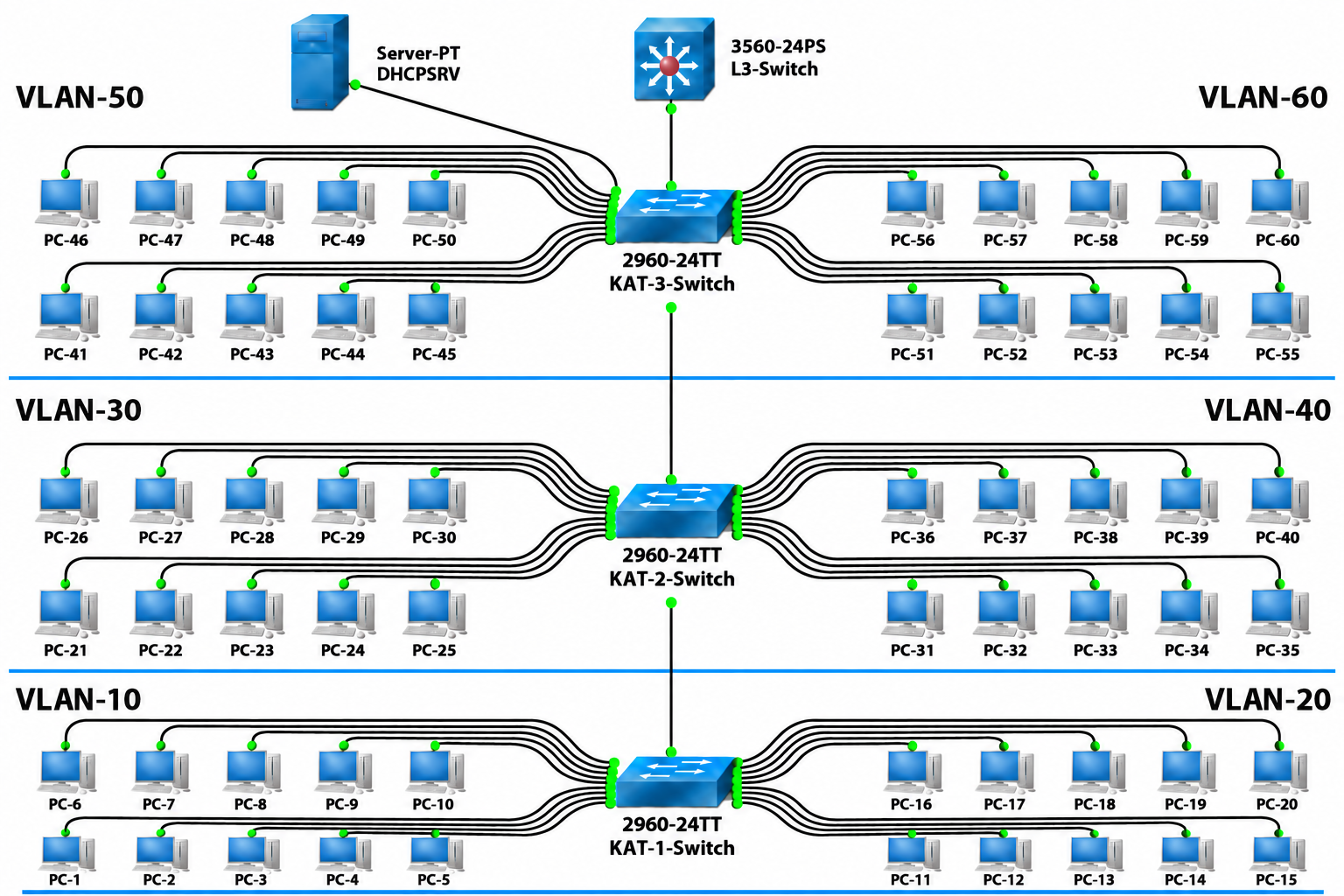
There is also a concrete benefit for management. When a user moves to another desk, it is enough to assign the port that the user connects to into the correct VLAN instead of changing the cable. A device that generates suspicious traffic can be isolated within its own VLAN, and because the logs can be read per VLAN, the segment that contains the fault is identified more quickly.
In this article, I first explain the VLAN types, then how a broadcast spreads in 2 networks, one without VLANs and one with VLANs configured, then 802.1Q tagging and how VTP works. After that, I apply VLAN creation, trunk, VTP, access port assignment, SVI, IP routing and DHCP relay configuration step by step in Cisco Packet Tracer, with 1 Layer 3 switch (Catalyst 3560) and 3 Layer 2 floor switches. DHCP server installation and scope creation are out of scope. I explained that subject in detail in my DHCP server installation and configuration article.
1- What Are the VLAN Types?
VLAN types describe the distinctions made according to the purpose of the traffic carried in a network. User data, management traffic, voice traffic and the traffic that travels untagged on a trunk have different needs, so each one is handled with a separate VLAN role. These types are not separate protocols. They are the same VLAN mechanism assigned to different tasks.
1.1- Data VLAN
A data VLAN is the VLAN that carries the daily data traffic of user devices. Computers, printers and other client devices connect to these VLANs. Some sources also call it a user VLAN. When I separate data VLANs by department or device group, the broadcast traffic of each group stays in its own segment and does not mix with voice or management traffic. All 6 VLANs that I define in this article are data VLANs.
1.2- Default VLAN
The default VLAN is the VLAN that all ports are assigned to when the switch first starts, and on Cisco switches it is VLAN 1. On a switch with no configuration, all ports are in VLAN 1, so the connected devices share the same broadcast domain and communicate with each other directly.
VLAN 1 cannot be deleted or renamed. For this reason, leaving user traffic, management traffic and sensitive data traffic on VLAN 1 is not recommended. Leaving unused ports open in VLAN 1 also means that any device connected to the network joins this VLAN directly.
1.3- Native VLAN
The native VLAN is the VLAN that the traffic carried untagged on an 802.1Q (Dot1q) trunk port belongs to. The frames of the other VLANs that pass over the trunk are marked with an 802.1Q tag. The frames of the native VLAN are sent without a tag. When the other end receives an untagged frame, it places the frame in its own native VLAN. On Cisco switches, the default native VLAN is VLAN 1.
This behaviour has a practical result. The native VLAN must be the same at both ends of the trunk. If different native VLANs are defined at the 2 ends, the untagged traffic from one side goes into a different VLAN on the other side, and the 2 VLANs mix with each other at Layer 2. Cisco devices report this condition over CDP with the NATIVE_VLAN_MISMATCH warning. In a production environment, it is recommended to set the native VLAN to a separate VLAN that is not assigned to any user port, and not to leave it on VLAN 1.
1.4- Management VLAN
The management VLAN is the VLAN reserved for remote management access to network devices such as switches and routers. When an IP address and a subnet mask are assigned to an interface (SVI) of this VLAN on the device, the device is accessed through this IP address with protocols such as SSH and SNMP. If no separate management VLAN is defined, VLAN 1 is used for management. For this reason, it is recommended to separate management traffic from the user VLANs and from VLAN 1.
SSH must be used for management access instead of Telnet. Telnet carries the whole session, including the user name and password, without encryption. Allowing access to the management VLAN only from the IP ranges where the management stations are located also reduces the surface for unauthorised access.
VLAN 60 - YONETIM, defined in this article, is a data VLAN defined for the management department of the company. It must not be confused with the management VLAN used for device management.
1.5- Voice VLAN
A voice VLAN is used to carry the voice traffic of IP phones in a VLAN that is separate from data traffic. On Cisco switches, both a data VLAN (switchport access vlan) and a voice VLAN (switchport voice vlan) are defined on the access port that the IP phone is connected to. The phone sends voice traffic in 802.1Q frames tagged with the ID of the voice VLAN and with a Layer 2 CoS value. The traffic of the computer connected behind the phone stays in the data VLAN. For this reason, an access port with a voice VLAN defined is the only access port type that carries tagged frames.
A voice VLAN alone does not guarantee voice quality. The VLAN separates the voice traffic, and Quality of Service (QoS) performs the prioritisation. The switch can be configured to trust the CoS priority assigned by the phone or to change this priority. Cisco recommends enabling QoS with mls qos and setting the port to trust the CoS value with mls qos trust cos before enabling the voice VLAN. The classification and scheduling steps of QoS ensure that voice packets, which are sensitive to delay and jitter, are not affected by heavy data traffic.
2- Broadcast Traffic in a Network Environment Without VLANs
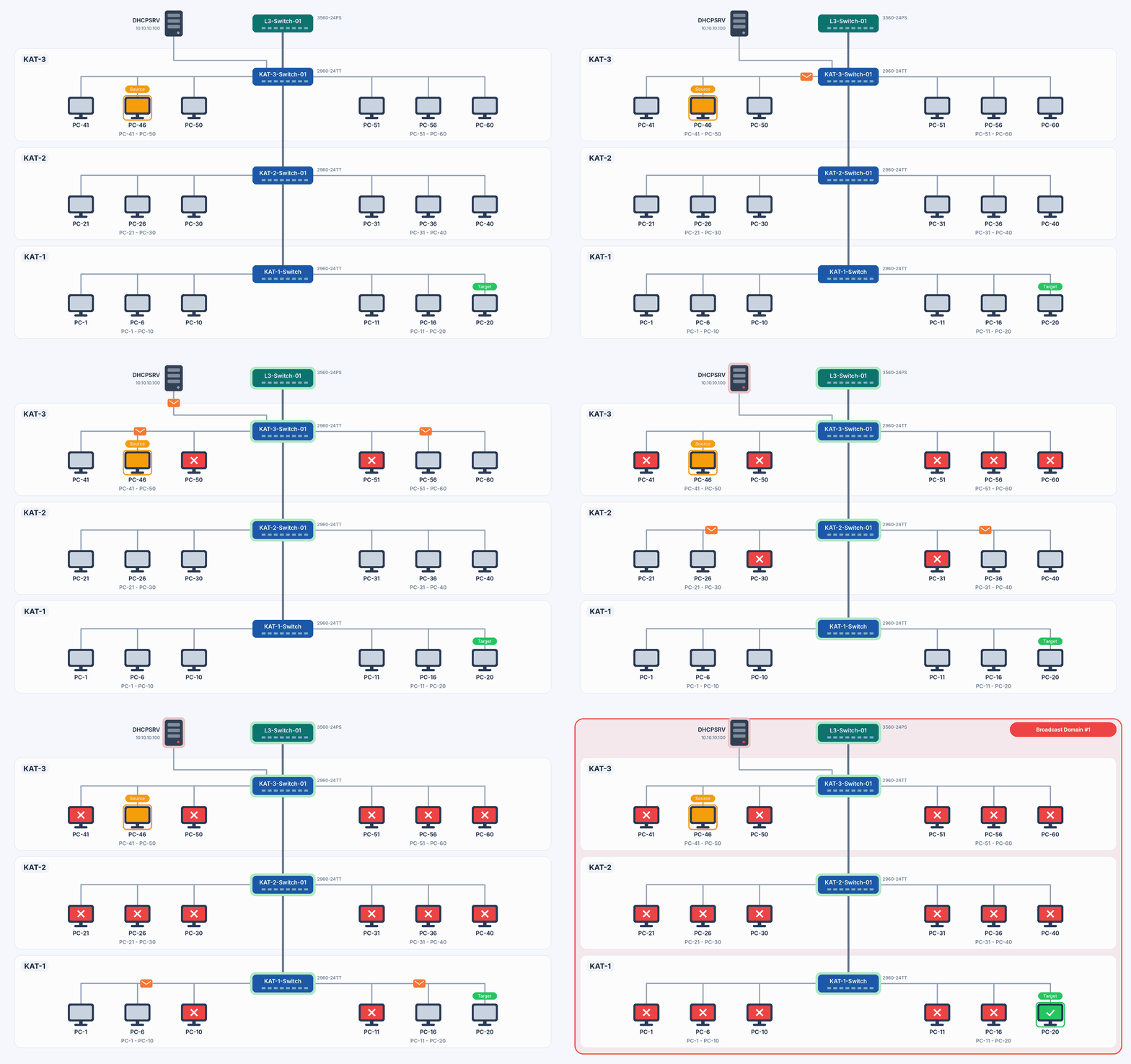
In a network with no VLANs configured, all ports are in VLAN 1, which is the default VLAN, and all devices on the 3 floors are in a single broadcast domain. In this design, I send a packet from PC-46 on floor 3 to PC-20 on floor 1. Because the 2 computers are in the same subnet, PC-46 wants to send the packet directly to PC-20, but it does not know the MAC address of PC-20 yet. For this reason, it broadcasts an ARP Request before it sends the actual data.
|
Step |
Source |
Packet |
Destination |
Transmission Type |
|
1 |
PC-46 |
ARP Request |
All devices |
Broadcast |
|
2 |
PC-20 |
ARP Reply |
PC-46 |
Unicast |
|
3 |
PC-46 |
Data |
PC-20 |
Unicast |
1. Because the destination MAC address of the ARP Request is FF-FF-FF-FF-FF-FF, the KAT-3 switch floods this frame to all ports except the port that PC-46 is connected to. On the same floor, the frame reaches the computers on floor 3 and the DHCP server, and over the trunk it reaches the L3 switch and the floor 2 switch. The floor 2 switch repeats the same operation, and the frame goes down to floor 1. As a result, a single ARP Request that concerns only PC-20 reaches all devices in the broadcast domain.
2. Each device that receives the frame compares the destination IP address in the ARP Request with its own IP address. Because the address does not belong to them, all devices except PC-20 discard the frame. PC-20, which owns the destination IP address, processes the request and adds the IP and MAC address of PC-46 to its own ARP table.
3. PC-20 sends an ARP Reply that contains its own MAC address. The ARP Reply is not a broadcast. It is a unicast frame that goes directly to the MAC address of PC-46. Because the switches recorded in their MAC address tables the port from which they learned the MAC address of PC-46 during the ARP Request, this frame is forwarded only through the ports that lead to PC-46.
4. After PC-46 learns the MAC address of PC-20, it sends the actual data to this MAC address as unicast. For the following packets, the MAC address of PC-20 is in the ARP cache, so no ARP Request is broadcast again.
The image is simplified to 3 computers from each department for clarity. In the real topology, the same ARP Request reaches all 60 computers on the 3 floors. Although the floors appear one after another in the simulation, the switches flood the broadcast almost simultaneously.
3- Broadcast Traffic in a Network Environment With VLANs Configured
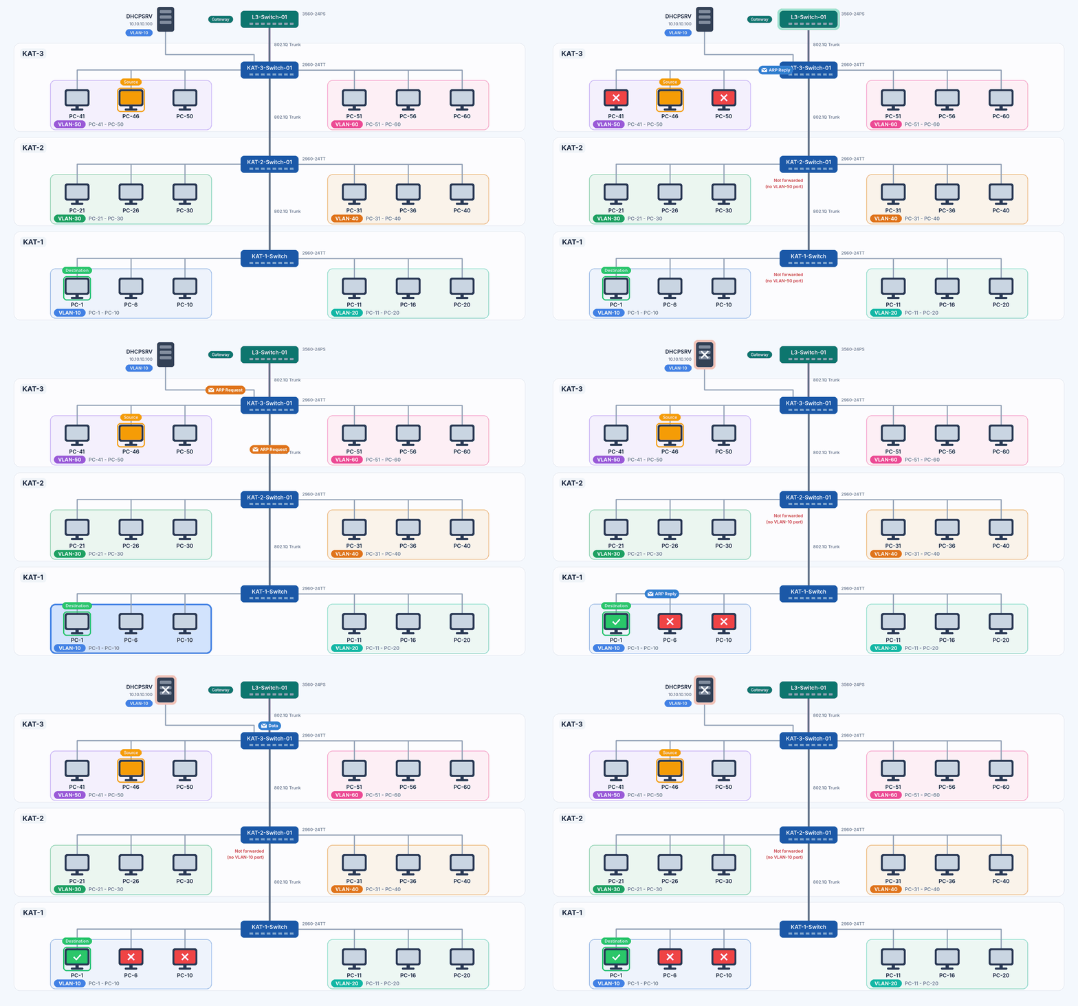
When VLANs are configured, the same physical topology is kept, but each VLAN becomes a separate broadcast domain. This time I send a packet from PC-46, which is in VLAN 50 on floor 3, to PC-1, which is in VLAN 10 on floor 1. Because the 2 computers are in different VLANs and therefore in different subnets, the packet does not go directly. It goes through the default gateway. In this design, the default gateway of each VLAN is the SVI created for that VLAN on the L3 switch.
|
Step |
Source |
Packet |
Destination |
Transmission Type |
|
1 |
PC-46 |
ARP Request |
Gateway (VLAN 50 SVI) |
Broadcast, VLAN 50 only |
|
2 |
Gateway |
ARP Reply |
PC-46 |
Unicast |
|
3 |
PC-46 |
Data |
Gateway |
Unicast |
|
4 |
Gateway (VLAN 10 SVI) |
ARP Request |
PC-1 |
Broadcast, VLAN 10 only |
|
5 |
PC-1 |
ARP Reply |
Gateway |
Unicast |
|
6 |
Gateway |
Data |
PC-1 |
Unicast |
1. PC-46 compares its own IP address and subnet mask with the IP address of PC-1 and understands that the destination is in another subnet. In this case, it has to send the packet to the default gateway, which is 10.10.50.254, the address of the VLAN 50 SVI. Because it does not know the MAC address of the gateway, it broadcasts an ARP Request for this address. This broadcast travels only within VLAN 50. The other computers in VLAN 50 discard the request, and the L3 switch accepts the request through the VLAN 50 SVI. No computer in the other VLANs receives this frame.
2. The L3 switch sends an ARP Reply that contains the MAC address of the VLAN 50 SVI to PC-46 as unicast.
3. PC-46 sends the actual packet. The destination IP address of this packet is the IP address of PC-1, and the destination MAC address is the MAC address of the gateway. The packet reaches the L3 switch as unicast.
4. The L3 switch checks its routing table and determines that the destination is in the directly connected 10.10.10.0/24 network, which is VLAN 10. If the MAC address of PC-1 is not in its own ARP table, it broadcasts an ARP Request for PC-1 through the VLAN 10 SVI. This broadcast is generated by the L3 switch, not by PC-46, and the frame travels only within VLAN 10. The DHCP server and the other computers in VLAN 10 discard the request, and PC-1 accepts it.
5. PC-1 sends an ARP Reply that contains its own MAC address to the L3 switch as unicast.
6. The L3 switch rewrites the Layer 2 header of the packet. It uses the MAC address of the VLAN 10 SVI as the source MAC address and the MAC address of PC-1 as the destination MAC address, and it decreases the TTL value by 1. The source and destination IP addresses do not change. The packet is delivered to PC-1 as unicast.
As shown, the broadcast does not leave its own VLAN at any stage. The ARP Request broadcast by PC-46 stays in VLAN 50, and the ARP Request broadcast by the L3 switch stays in VLAN 10. The only traffic carried between the VLANs is routed unicast packets. After the MAC addresses of the gateway and PC-1 are placed in the ARP cache, no broadcast occurs in any VLAN for the following packets. The reply that PC-1 sends to PC-46 follows the same logic and first goes through its own gateway, the VLAN 10 SVI.
The image shows that the VLAN 50 broadcast also reaches the floor 2 and floor 1 switches over the trunk. In this design, the trunks allow all VLANs by default and VTP Pruning is disabled, so the broadcast is sent to all trunks that carry VLAN 50. Because these switches have no access port assigned to VLAN 50, the frame is not forwarded to any computer. To prevent unnecessary trunk traffic, only the required VLANs can be allowed on the trunk, or VTP Pruning can be enabled.
4- How 802.1Q and the Trunk Link Work
When a VLAN extends across more than 1 switch, a trunk link that carries all VLANs over a single physical connection is used instead of a separate cable between the switches for each VLAN. A trunk port is a port that carries the traffic of more than 1 VLAN over the same link, and it is generally used between switches or between a switch and a router. The other side understands which VLAN a frame belongs to from the VLAN tag added to the frame.
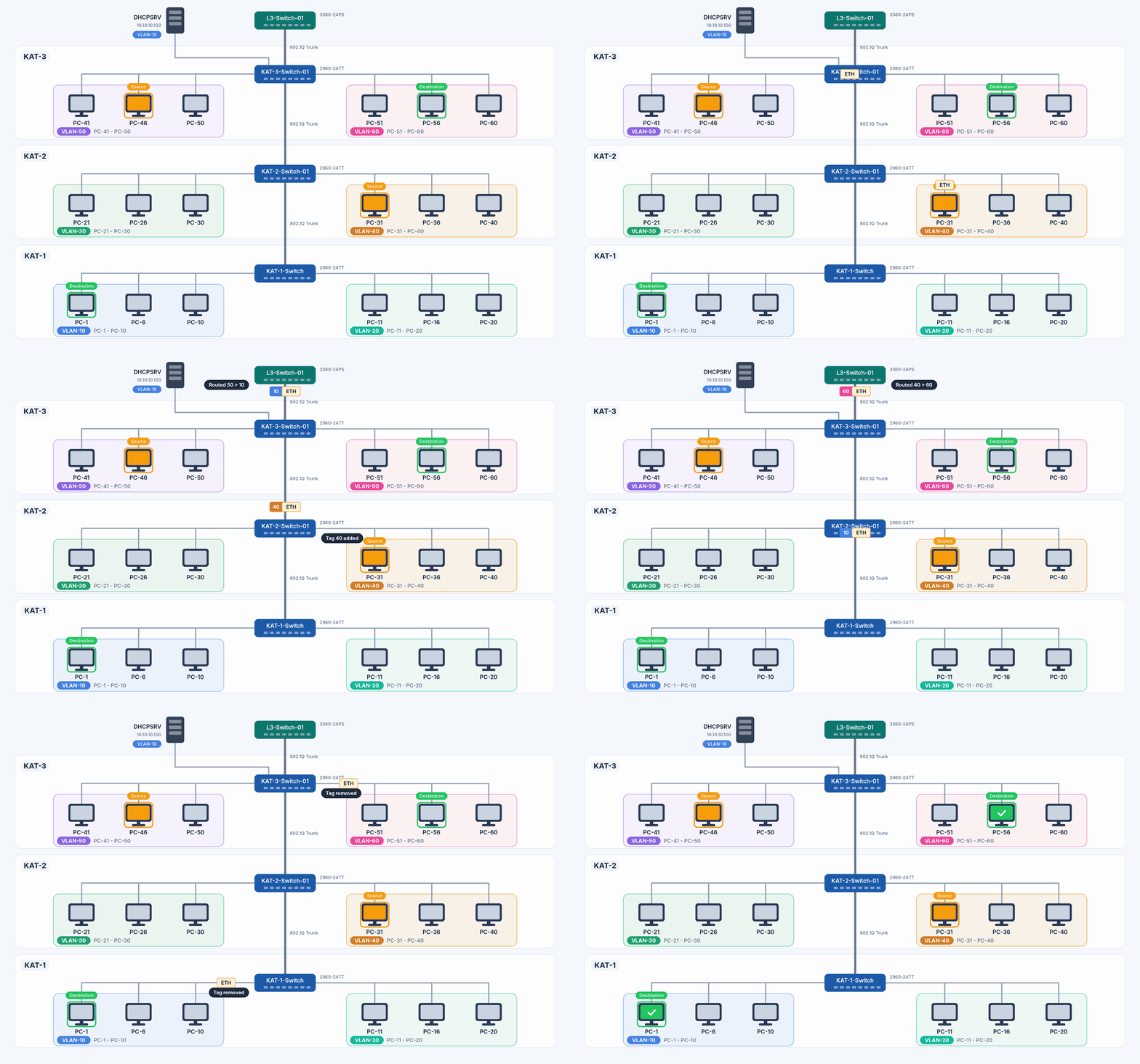
In the image, 2 flows progress at the same time. The frame sent by PC-46 reaches the KAT-3 switch untagged from the access port and receives the VLAN 50 tag when it leaves on the trunk. The L3 switch receives the frame through the VLAN 50 SVI, removes the tag, routes the packet to VLAN 10 and sends it back over the trunk with the VLAN 10 tag. The frame passes through the KAT-3 and KAT-2 switches with its tag unchanged, and the KAT-1 switch removes the tag and delivers the frame to PC-1 untagged. The flow from PC-31 to PC-56 starts in the same way with the VLAN 40 tag and continues with the VLAN 60 tag. In this way, frames that belong to different VLANs are carried on the same trunk link without mixing with each other, because of their tags.
The 802.1Q (Dot1q) Standard
802.1Q is the standard defined by the Institute of Electrical and Electronics Engineers (IEEE) that specifies how VLAN information is added to an Ethernet frame. A 4-byte 802.1Q tag is added to an Ethernet frame sent over a trunk. This tag contains the VLAN ID that the frame belongs to and the priority information known as 802.1p. The VLAN ID allows the other switch to place the frame in the correct VLAN. The priority field is used to prioritise delay-sensitive traffic such as voice with QoS.
The tag is added when the frame leaves a trunk port and is removed when the frame is delivered to an end device from an access port. Except in the voice VLAN scenario, the end device never sees the VLAN tag. The frames of the native VLAN travel untagged on the trunk as well.
Carrying only the VLANs that are really required over a trunk is the correct approach for both security and unnecessary flood traffic. On Cisco switches, a trunk allows all VLANs by default and uses VLAN 1 as the native VLAN. I did not change these defaults in this configuration.
5- How VTP (VLAN Trunking Protocol) Works
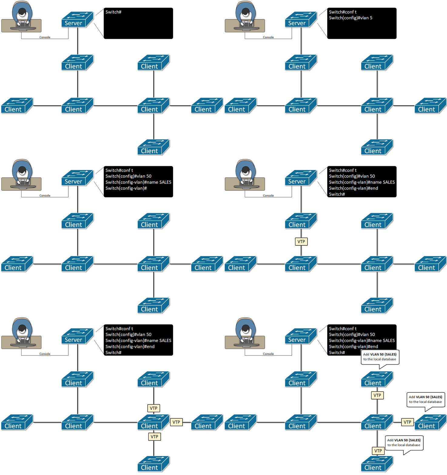
VTP (VLAN Trunking Protocol) is a Layer 2 messaging protocol that distributes VLAN addition, deletion and renaming information between Cisco switches. When I create a VLAN on a switch in server mode, this information is sent as an advertisement over the trunk links to the other switches in the same VTP domain. In this way, I do not need to enter the VLANs on each switch one by one. VTP does not assign VLANs to ports. Which port is in which VLAN is configured separately on each switch.
VTP advertisements are sent and received only over trunk ports. For this reason, the trunk links between the switches must be established first for VTP to work. VTP v1 and v2 distribute only the normal-range VLANs (1-1005).
VTP Domain
A VTP domain is the area that consists of switches that are under the same administrative responsibility and share the same domain name. A switch can belong to only 1 VTP domain. All switches in server and client mode must use the same domain name. Otherwise, advertisements with a different domain name are ignored.
The domain name can be entered manually on each switch. When a switch with no domain name defined receives a VTP advertisement over a trunk, it takes the domain name and the configuration revision number from this advertisement. If a password is defined for the domain, the switch learns the domain name only after the correct password is entered. I did not enter the domain name manually on the floor switches. They learned it from the L3 switch after the password was defined.
VTP Password
A VTP password is not mandatory, but if it is defined, it must be the same on all switches in the domain and must be entered on each switch separately. A switch that has no password or has the wrong password rejects the incoming VTP advertisements and does not receive VLAN information. This also makes it harder for an unauthorised switch connected to the network to change the VLAN structure of the domain.
The Catalyst 3560 and 2960 configuration guides give a range of 8 to 64 characters for the VTP password. The value 123456 used in this configuration is accepted in Packet Tracer. On real devices, a password within this range must be used.
VTP Version 2
VTP runs version 1 by default. The Cisco documentation defines the differences that version 2 introduces compared with version 1 under 4 headings:
|
Feature |
VTP Version 2 Behaviour |
|
Token Ring support |
Supports TrBRF and TrCRF Token Ring VLANs. |
|
Unrecognized TLV support |
A server or client also forwards changes that contain TLVs it cannot parse to its other trunks. |
|
Transparent mode behaviour |
In version 1, a transparent switch forwards the message only if the domain name and version match. In version 2, the version check is removed. In the current IOS XE documentation the domain name check remains, whereas in the older 3560 documentation the message is forwarded without a check. |
|
Consistency checks |
Consistency checks for VLAN names and values are performed only on information entered locally through the CLI or SNMP. They are not performed on information received in a VTP message or read from NVRAM. If the MD5 digest is correct, the information is accepted. |
Version 1 and version 2 do not work together in the same domain. Version 2 must be enabled only if all switches in the domain support it. When version 2 is enabled on the server, all switches that support version 2 also change to version 2. The version can be changed only on a switch in server or transparent mode. This is the reason why I entered the vtp version 2 command before the vtp mode client command on the floor switches. At that moment, the switch was still in server mode, which is its default mode.
VTP version 3 introduces the primary server, a hidden password, distribution of extended VLANs in the 1006-4094 range and private VLAN support. The configuration in this article is done with version 2.
VTP Mode
The VTP mode determines how a switch creates, advertises and receives VLAN information. On Catalyst switches that run Cisco IOS and IOS XE, including the Catalyst 3560 that I use in this configuration, the default mode is server. This behaviour is not the same on all Cisco platforms. For example, on the Nexus 9000 series, VTP is disabled by default and the mode is transparent. For this reason, the L3 switch runs in server mode without an additional command, and the floor switches were also in server mode until they were set to client mode.
|
Feature |
VTP Server |
VTP Client |
VTP Transparent |
|
Create, modify and delete VLANs |
Yes, the change is distributed to the whole domain |
No |
Yes, only on itself |
|
Advertises its own VLAN configuration |
Yes |
Yes |
No |
|
Synchronises with incoming advertisements |
Yes |
Yes |
No |
|
Forwards incoming advertisements to other trunks |
Yes |
Yes |
In version 1 if the domain and version match, in version 2 yes |
|
Stores the VLAN configuration in NVRAM (v1 and v2) |
Yes |
No |
Yes |
There can be more than 1 server in the same domain. Cisco even recommends that all switches in the domain run in server mode if the NVRAM and DRAM capacity is sufficient. However, the design of VTP is based on making changes from a single switch. Making changes on more than 1 server at the same time can cause inconsistency in the VLAN database. In addition to these modes, current IOS XE releases also have a VTP off mode, which behaves like transparent mode but does not forward advertisements.
Configuration Revision Number
In VTP, the configuration revision number, not the VTP version, determines which VLAN information is valid. Each VLAN change made on the server increases this number by 1. When a switch receives a valid advertisement with the same domain name and a revision number higher than its own, it replaces its own VLAN database with this information. It ignores advertisements that carry a lower revision number.
This mechanism also brings the biggest operational risk of VTP. When a switch that was used in another environment and has a revision number higher than the one in the domain is connected to the domain, its VLAN list spreads to the whole domain. The VLANs that do not exist on this switch are deleted from the other switches as well, and the ports assigned to these VLANs can no longer carry traffic.
In VTP v1 and v2, adding a switch with a revision number higher than the one in the domain can delete the VLAN information in the whole domain. Before you add a new switch, check its revision number with show vtp status.
6- Network Topology and VLAN Plan
The network topology was built in Cisco Packet Tracer with the following components.
|
Component |
Quantity |
Role |
|
Layer 3 Cisco switch (Catalyst 3560, backbone) |
1 |
VTP server where the VLANs are created, SVIs, IP routing and DHCP relay |
|
24-port Layer 2 Cisco switch |
3 |
1 on each floor, VTP client and user access ports |
|
PC |
60 |
Clients in the department VLANs |
|
DHCP server |
1 |
In VLAN 10, IP address assignment to all VLANs with the IP address 10.10.10.100 |
Each floor has 2 departments and 1 VLAN for each department. The plan below shows on which switch and to which port range the VLANs are assigned, and which IP block they use. The default gateway addresses are the IP addresses of the SVIs created for each VLAN on the L3 switch.
|
VLAN ID |
VLAN Name |
Switch |
Access Ports |
Subnet |
Default Gateway |
|
10 |
IT |
KAT-1-Switch-01 |
Fa0/1-10 |
10.10.10.0/24 |
10.10.10.254 |
|
20 |
IK |
KAT-1-Switch-01 |
Fa0/11-20 |
10.10.20.0/24 |
10.10.20.254 |
|
30 |
ARGE |
KAT-2-Switch-01 |
Fa0/1-10 |
10.10.30.0/24 |
10.10.30.254 |
|
40 |
MUHENDISLIK |
KAT-2-Switch-01 |
Fa0/11-20 |
10.10.40.0/24 |
10.10.40.254 |
|
50 |
FINANS |
KAT-3-Switch-01 |
Fa0/1-10 |
10.10.50.0/24 |
10.10.50.254 |
|
60 |
YONETIM |
KAT-3-Switch-01 |
Fa0/11-20 |
10.10.60.0/24 |
10.10.60.254 |
7- Creating VLANs on the L3 Switch
I create the VLANs on the L3 switch, which has the backbone role. These VLANs are distributed to the floor switches with VTP when the steps in section 9- VTP Configuration are completed. In this configuration, I create the VLANs before I define the VTP domain name, and Packet Tracer accepts this order. VLAN information is not distributed to the other switches before the domain name is defined.
According to the Catalyst 3560 guide, a VLAN cannot be created on a VTP server before the domain name is defined. On a real device, the vtp domain xyz command must be entered first, and then the VLANs.
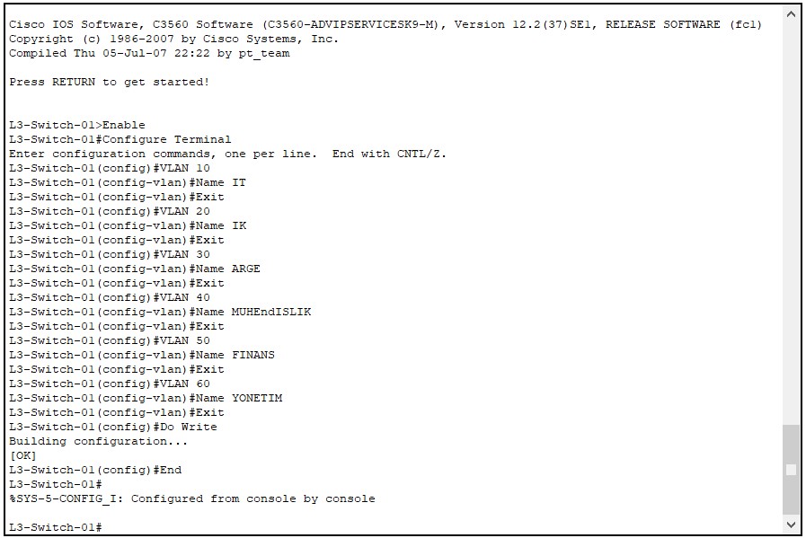
Step 1 - Creating the VLANs
I enter global configuration mode, create the 6 VLANs and give each one its department name. The vlan command enters VLAN configuration mode, and the name command names the VLAN.
enable
configure terminal
vlan 10
 name IT
 exit
vlan 20
 name IK
 exit
vlan 30
 name ARGE
 exit
vlan 40
 name MUHENDISLIK
 exit
vlan 50
 name FINANS
 exit
vlan 60
 name YONETIM
 end
Step 2 - Checking the Created VLANs
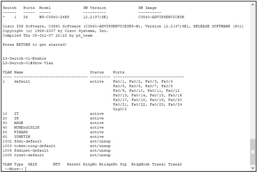
I list the VLANs that I created with the show vlan command in privileged EXEC mode.
Checkpoint
VLAN 10, 20, 30, 40, 50 and 60 must appear in the list with the given names and in the active state. Because they are not assigned to any port yet, their port columns are empty.
8- VLAN Trunk Configuration
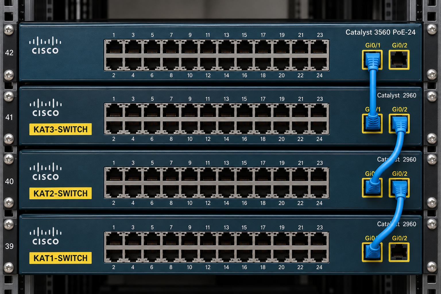
Each floor switch has 2 different VLANs (for example, VLAN 10 and VLAN 20 on KAT-1-Switch-01). I configure the ports that connect the switches to each other as trunks, so that the traffic of these VLANs can reach the L3 switch and the other floors, and so that VTP advertisements can be carried between the switches.
Step 3 - Trunk Configuration on the Backbone Switch
I configure a trunk on gigabitEthernet 0/1, the port of the L3 switch that connects to the floor switches. Because the Catalyst 3560 supports both ISL and 802.1Q trunk encapsulation, I first select 802.1Q with switchport trunk encapsulation dot1q. On this model, the port cannot be set statically to trunk mode before the encapsulation is selected. Then I set the port permanently to trunk mode with switchport mode trunk.
enable
configure terminal
interface gigabitEthernet 0/1
 switchport trunk encapsulation dot1q
 switchport mode trunk
 end
Setting a port that is in use to trunk mode can interrupt the traffic that passes through that port for a short time. In a production environment, this change must be made in a maintenance window.
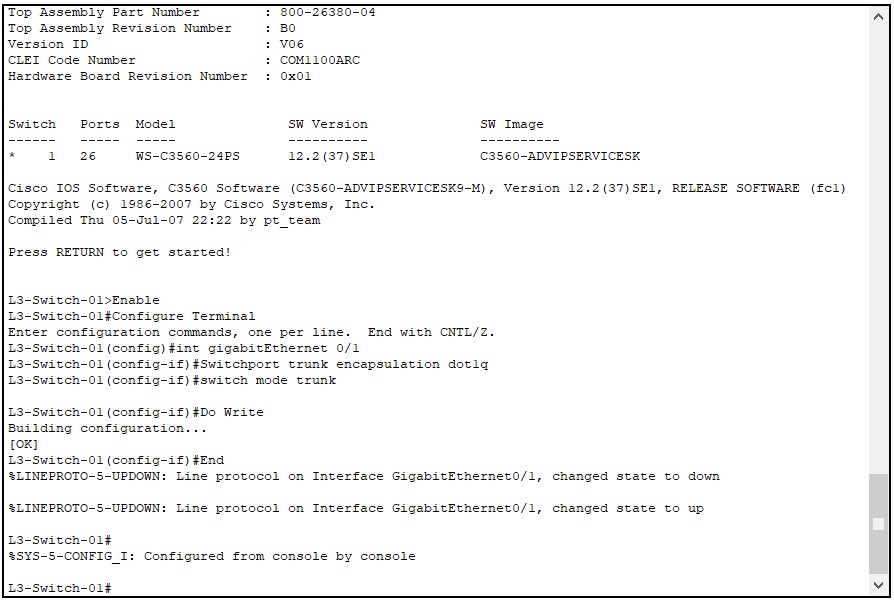
Step 4 - Checking the Trunk on the Backbone Switch
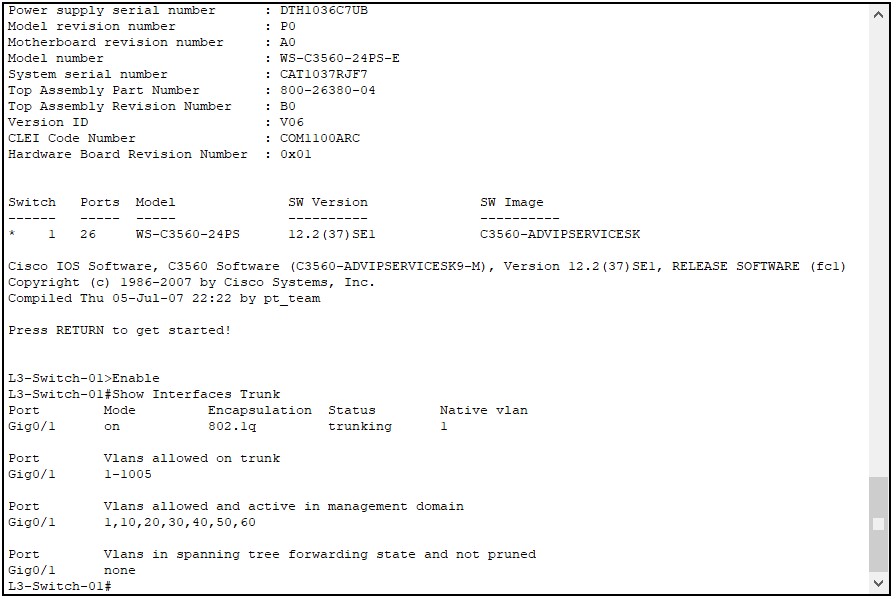
show interfaces trunk
Checkpoint
Gi0/1 must appear in the list in the trunking state and with 802.1q encapsulation. The native VLAN column shows 1, which is the default value.
Step 5 - Trunk Configuration on KAT-3-Switch-01
I set the gigabitEthernet 0/1 and gigabitEthernet 0/2 ports of KAT-3-Switch-01, which connect to the switches, to trunk mode. I did not enter the encapsulation line on the floor switches. On these switches, the trunk was established with the switchport mode trunk command only.
enable
configure terminal
interface gigabitEthernet 0/1
 switchport mode trunk
 exit
interface gigabitEthernet 0/2
 switchport mode trunk
 end
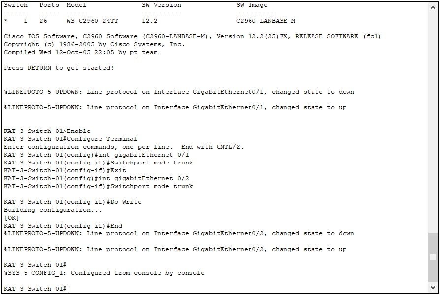
Step 6 - Checking the Trunk on KAT-3-Switch-01
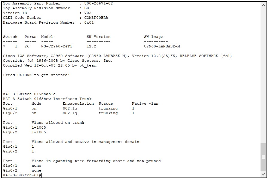
show interfaces trunk
Checkpoint
The Gi0/1 and Gi0/2 ports must appear in the trunking state.
Step 7 - Trunk Configuration on KAT-2-Switch-01
I apply the same configuration to the gigabitEthernet 0/1 and gigabitEthernet 0/2 ports of KAT-2-Switch-01.
enable
configure terminal
interface gigabitEthernet 0/1
 switchport mode trunk
 exit
interface gigabitEthernet 0/2
 switchport mode trunk
 end
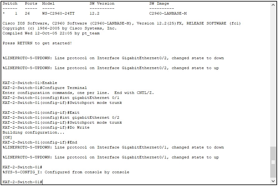
Step 8 - Checking the Trunk on KAT-2-Switch-01
show interfaces trunk
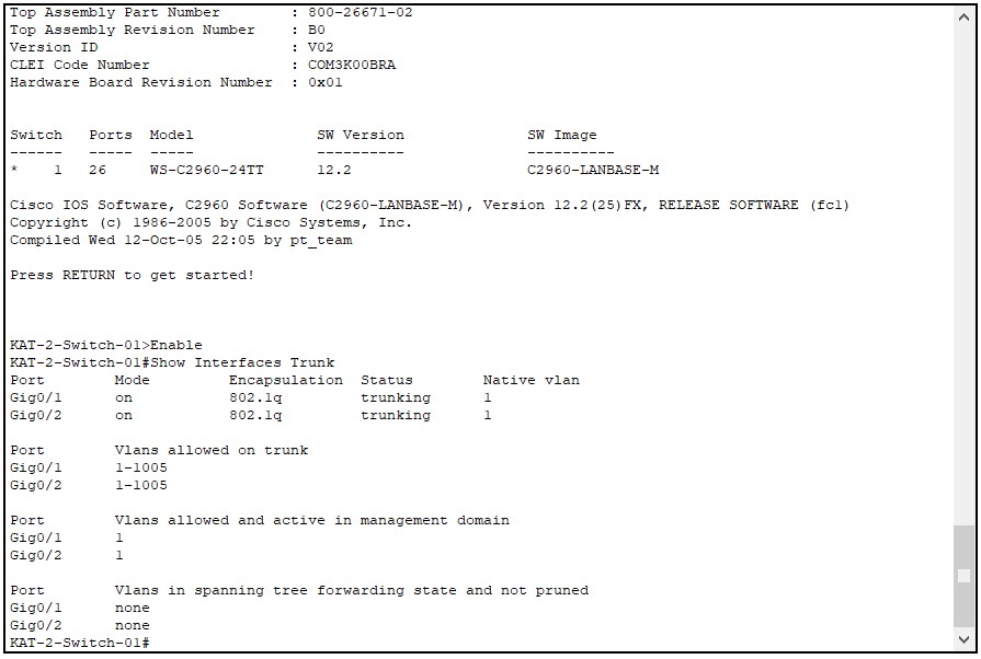
Checkpoint
The Gi0/1 and Gi0/2 ports must appear in the trunking state.
Step 9 - Trunk Configuration on KAT-1-Switch-01
Finally, I set the gigabitEthernet 0/1 and gigabitEthernet 0/2 ports of KAT-1-Switch-01 to trunk mode.
enable
configure terminal
interface gigabitEthernet 0/1
 switchport mode trunk
 exit
interface gigabitEthernet 0/2
 switchport mode trunk
 end
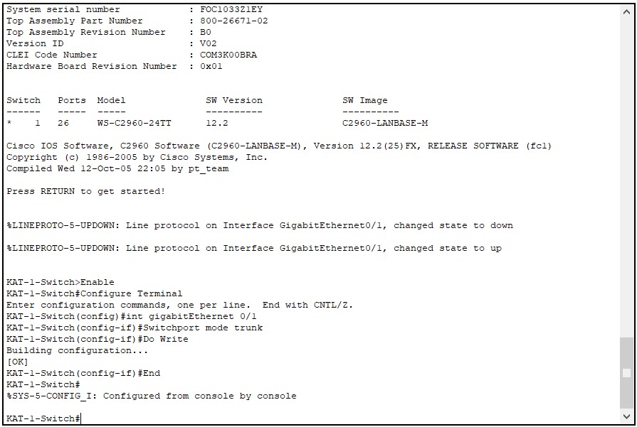
Step 10 - Checking the Trunk on KAT-1-Switch-01
show interfaces trunk
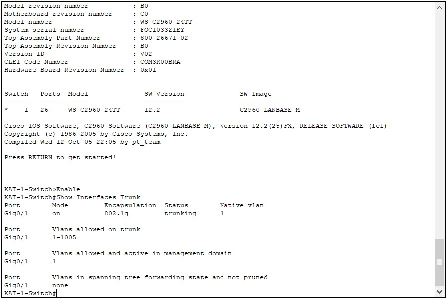
Checkpoint
The Gi0/1 and Gi0/2 ports must appear in the trunking state.
9- VTP Configuration
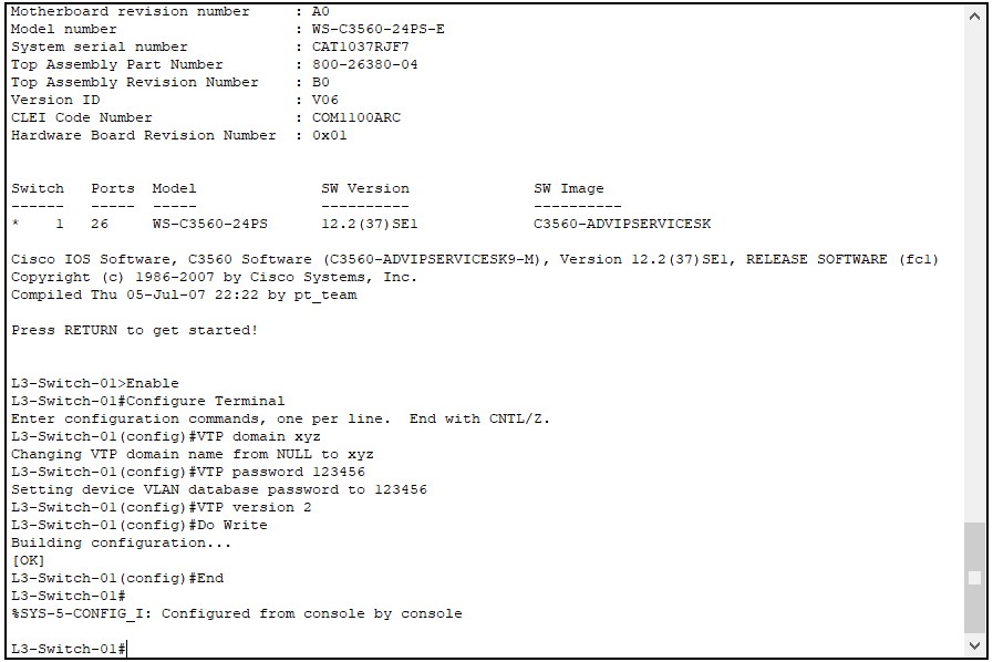
Now that the trunk links are ready, VTP advertisements can be carried between the switches. I leave the L3 switch as the VTP server and define the domain name, the password and the version. I set the floor switches to client mode with the same password and version. I do not enter the domain name on the floor switches. After the password is defined, they learn it from the advertisement that comes from the L3 switch.
Step 11 - VTP Configuration on the L3 Switch
Because the L3 switch runs in server mode by default, I do not need to enter the vtp mode server command. I define the domain name as xyz and the password as 123456, and I enable version 2.
enable
configure terminal
vtp domain xyz
vtp password 123456
vtp version 2
end
When version 2 is enabled on the server, all switches in the domain that support version 2 change to version 2. If the domain contains a switch that supports only version 1, that switch cannot receive VTP information.
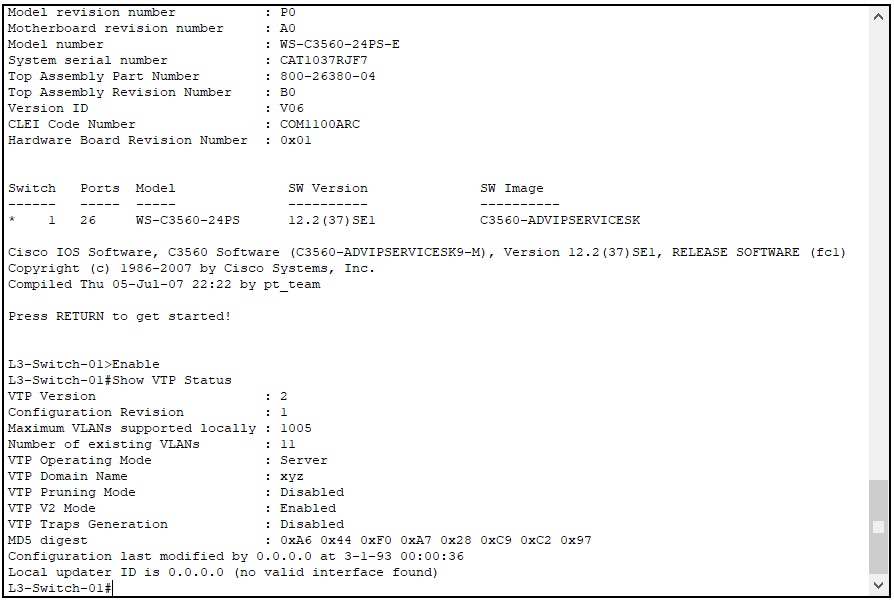
Step 12 - Checking the VTP Status on the L3 Switch
Checkpoint
The VTP Operating Mode field must show Server, the VTP Domain Name field must show xyz, and version 2 must be enabled. Because VLANs were created in Step 1, the Configuration Revision value is greater than 0.
Step 13 - VTP Configuration on KAT-3-Switch-01
On KAT-3-Switch-01, I define the password and the version and set the switch to client mode. The command order is important: because the version can be changed only in server or transparent mode, I enter the vtp version 2 command before the vtp mode client command, while the switch is still in the default server mode.
enable
configure terminal
vtp password 123456
vtp version 2
vtp mode client
end
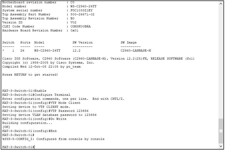
A switch in client mode does not create the VLAN database file (vlan.dat). On real devices, the vtp domain xyz command must be entered before the vtp mode client command so that the VTP settings are kept after a restart.
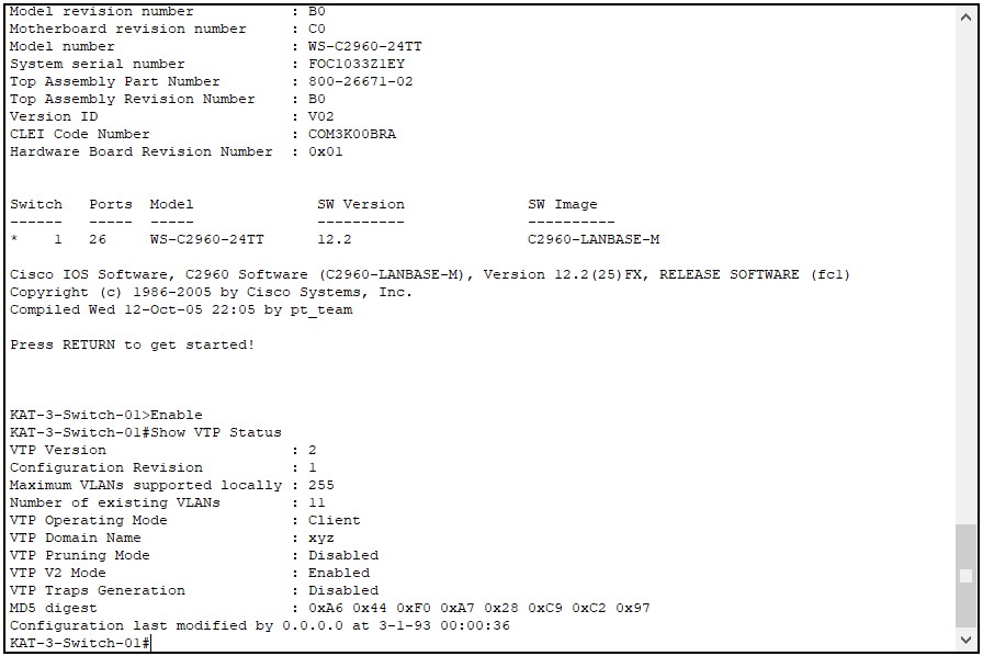
Step 14 - Checking the VTP Status on KAT-3-Switch-01
Checkpoint
The VTP Operating Mode field must show Client, and the VTP Domain Name field must show xyz, which was learned from the L3 switch. The Configuration Revision value must be the same as the value on the L3 switch.
Step 15 - VTP Configuration on KAT-2-Switch-01
enable
configure terminal
vtp password 123456
vtp version 2
vtp mode client
end
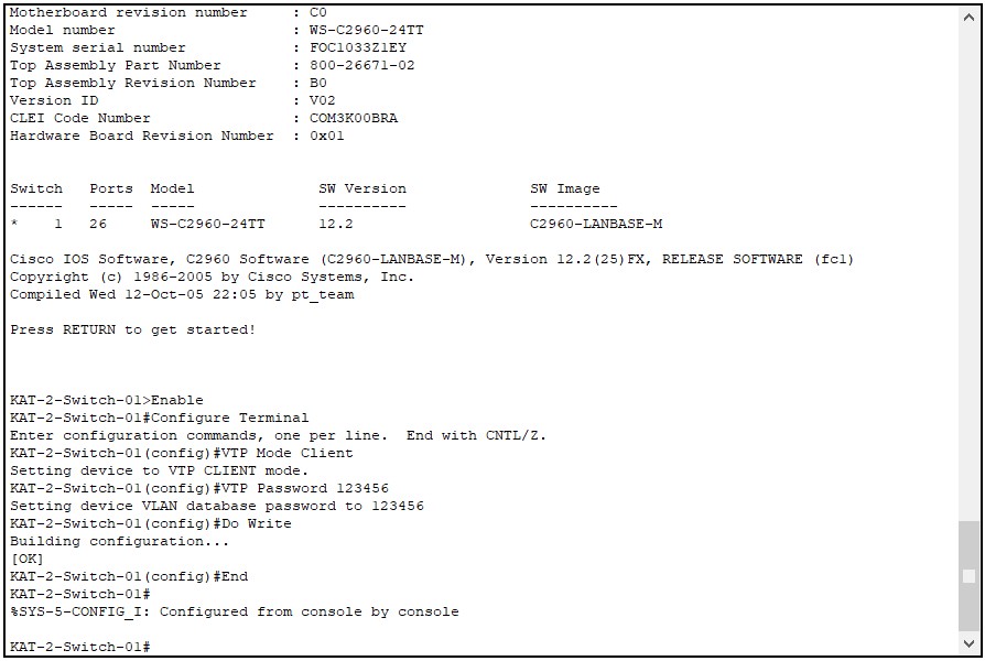
Step 16 - Checking the VTP Status on KAT-2-Switch-01
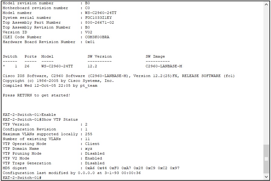
Checkpoint
The mode must be Client, the domain name must be xyz, and the Configuration Revision value must match the L3 switch.
Step 17 - VTP Configuration on KAT-1-Switch-01
On KAT-1-Switch-01, the password must also be the same as on the other switches in the domain. If a different password is entered, the switch rejects the advertisements that come from the L3 switch and does not receive VLAN information.
enable
configure terminal
vtp password 123456
vtp version 2
vtp mode client
end
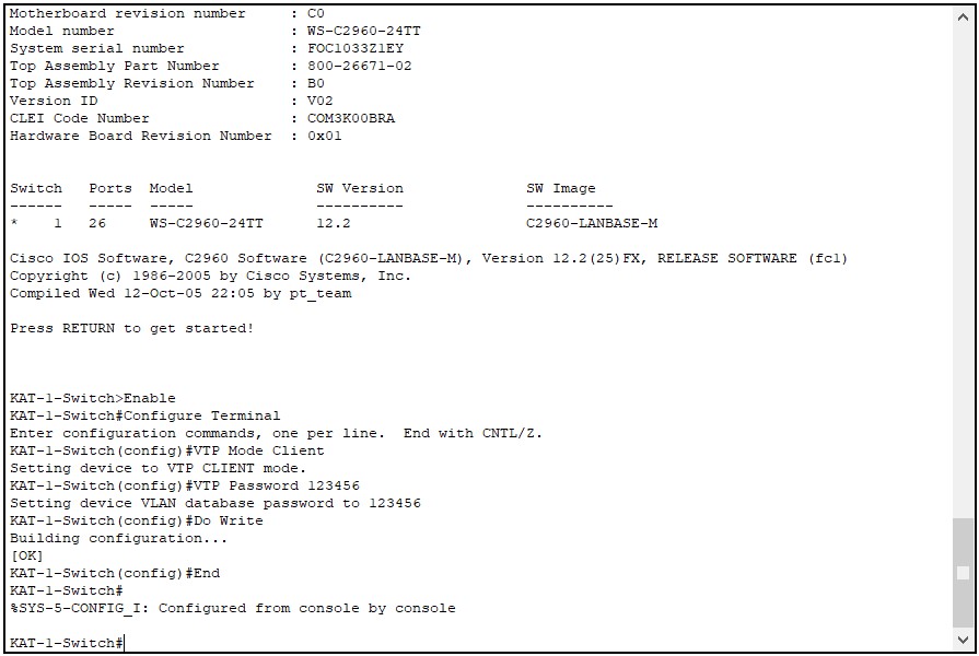
Step 18 - Checking the VTP Status on KAT-1-Switch-01
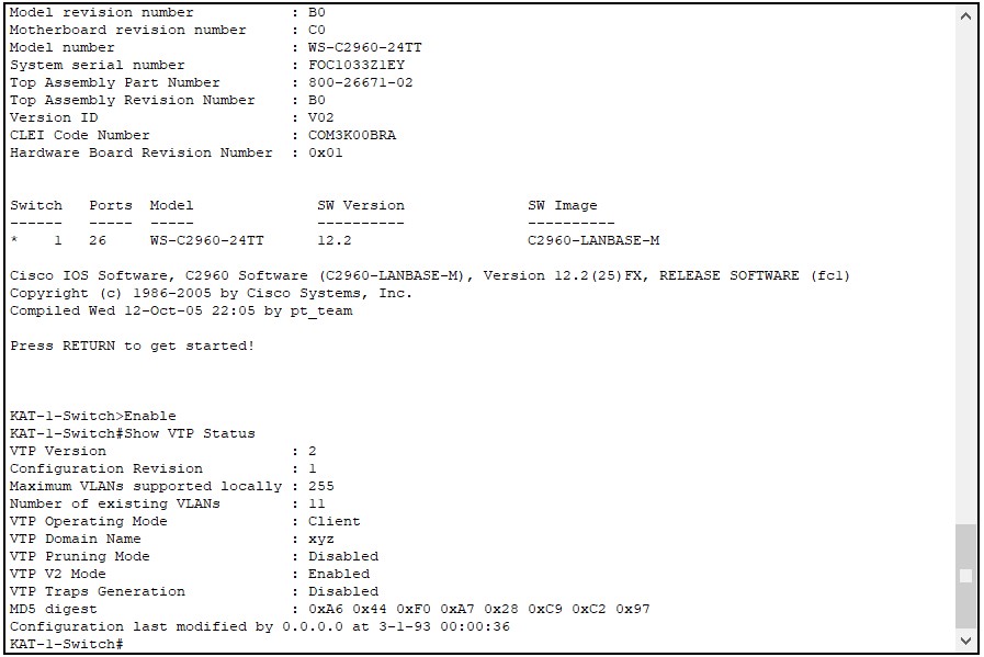
Checkpoint
The mode must be Client, the domain name must be xyz, and the Configuration Revision value must match the L3 switch.
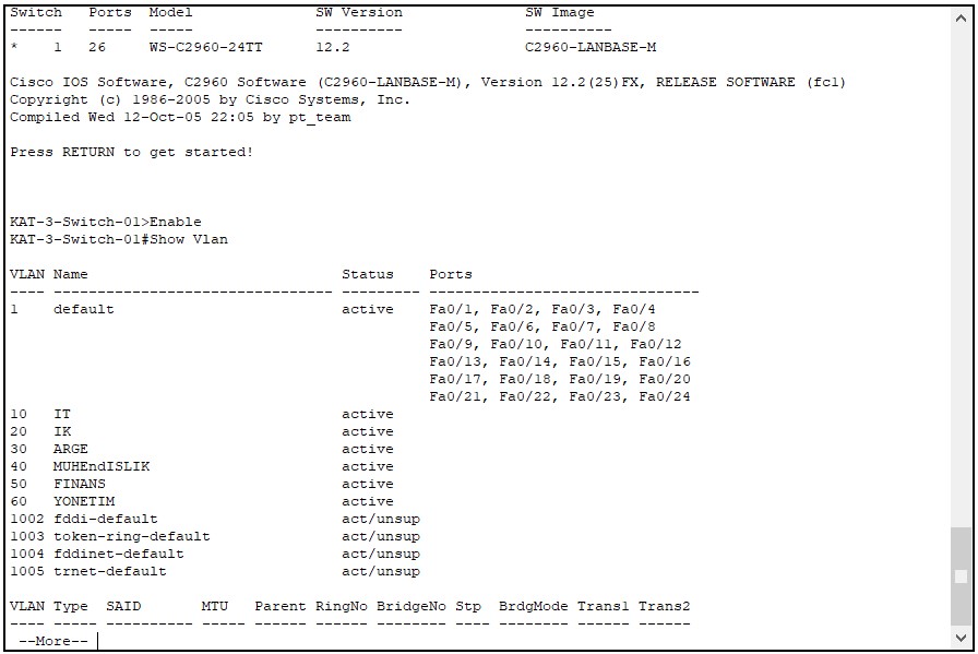
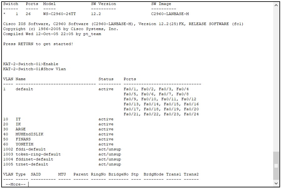
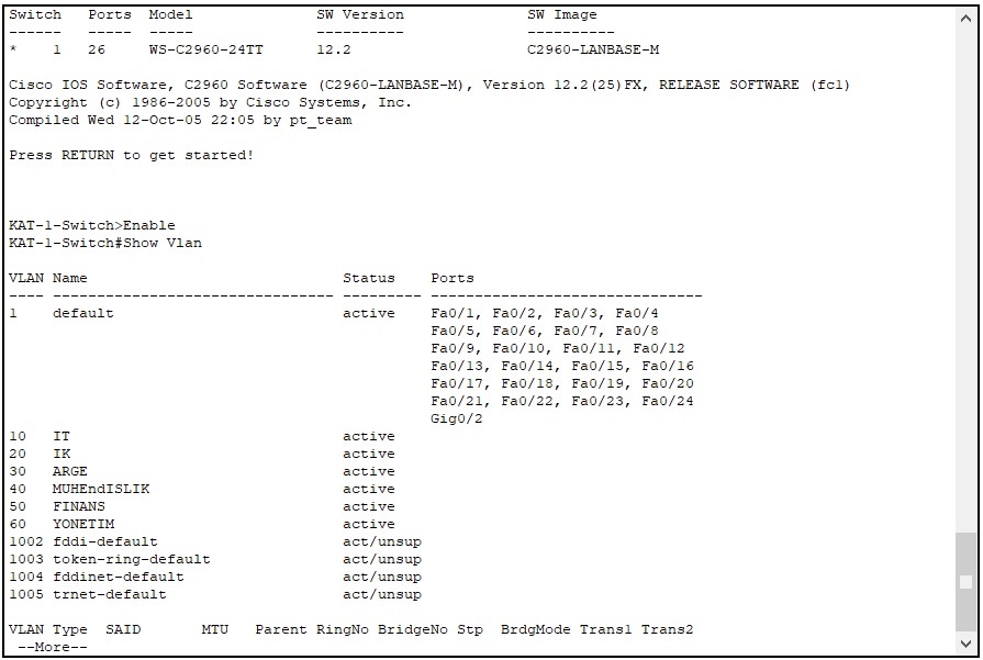
Step 19 - Checking That the VLANs Are Distributed to the Floor Switches
After the VTP configuration is complete, I run the show vlan command on each floor switch. Here I see that the VLANs that I created on the L3 switch have been transferred to the floor switches.
VLAN status on KAT-3-Switch-01:
VLAN status on KAT-2-Switch-01:
VLAN status on KAT-1-Switch-01:
Checkpoint
VLAN 10-60 must be listed with their names on all 3 floor switches. If the VLANs do not appear on a switch, first check the VTP password and the trunk status of that switch.
10- Assigning VLANs to Switch Ports
The VLANs distributed with VTP are now defined on the floor switches, but they are not assigned to any switch port yet. On each floor, I assign the first 10 ports to the VLAN of one department and the next 10 ports to the VLAN of the other department. The 3 commands that I use in this operation do the following:
interface range fastEthernet 0/1-10 selects more than 1 port at once. The commands that follow are applied to all selected ports at the same time.
switchport mode access makes the port a permanent access port. An access port belongs to a single data VLAN and exchanges untagged frames with the end device. This command also prevents the port from becoming a trunk unintentionally through a DTP (Dynamic Trunking Protocol) negotiation with a device connected to it. On ports where an IP phone is connected, a voice VLAN is defined in addition to the access VLAN, and these ports carry the voice traffic of the phone tagged.
switchport access vlan 10 sets the VLAN that the port belongs to. If this command is not entered, the access port stays in VLAN 1 by default.
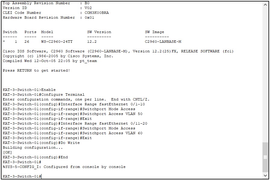
Step 20 - Port Assignment on KAT-3-Switch-01
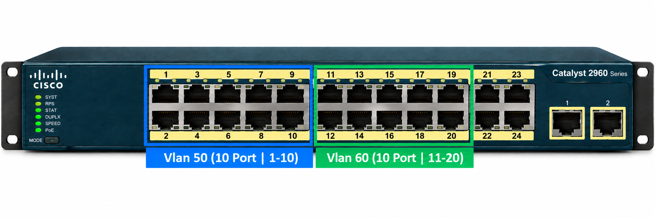
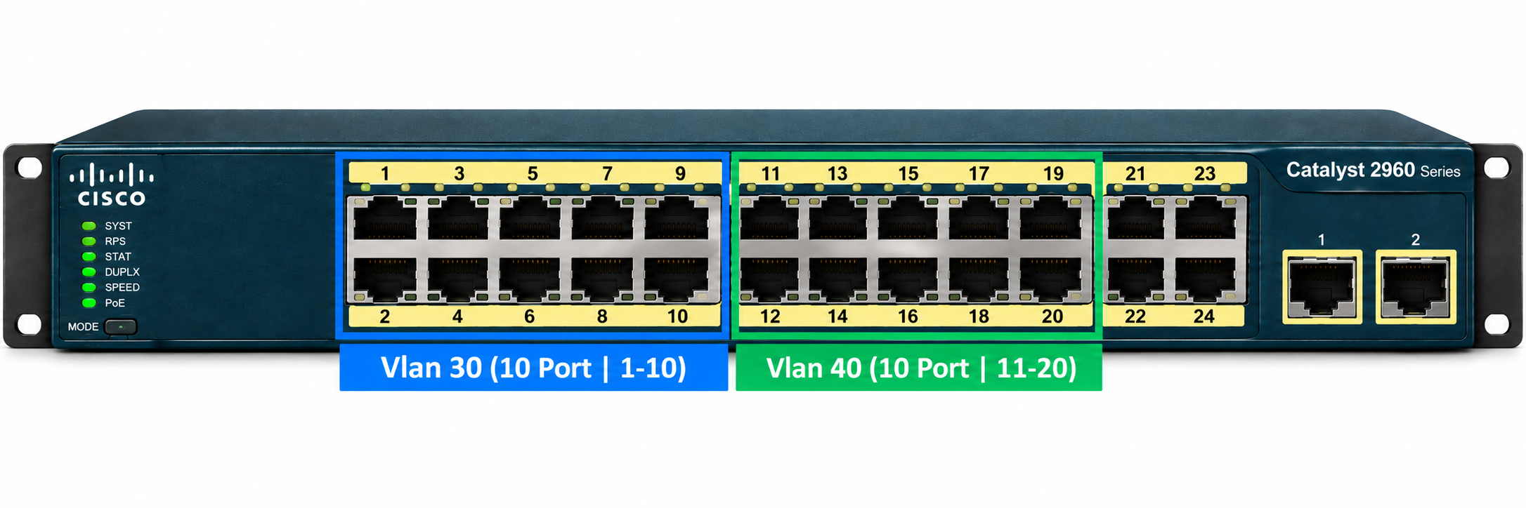
Floor 3 has the FINANS and YONETIM departments. I assign the fastEthernet 0/1-10 ports to VLAN 50 for FINANS and the fastEthernet 0/11-20 ports to VLAN 60 for YONETIM.
enable
configure terminal
interface range fastEthernet 0/1-10
 switchport mode access
 switchport access vlan 50
 exit
interface range fastEthernet 0/11-20
 switchport mode access
 switchport access vlan 60
 end
Step 21 - Port Assignment on KAT-2-Switch-01
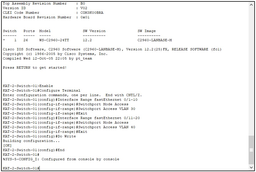
Floor 2 has the ARGE and MUHENDISLIK departments. I assign the fastEthernet 0/1-10 ports to VLAN 30 for ARGE and the fastEthernet 0/11-20 ports to VLAN 40 for MUHENDISLIK.
enable
configure terminal
interface range fastEthernet 0/1-10
 switchport mode access
 switchport access vlan 30
 exit
interface range fastEthernet 0/11-20
 switchport mode access
 switchport access vlan 40
 end
Step 22 - Port Assignment on KAT-1-Switch-01
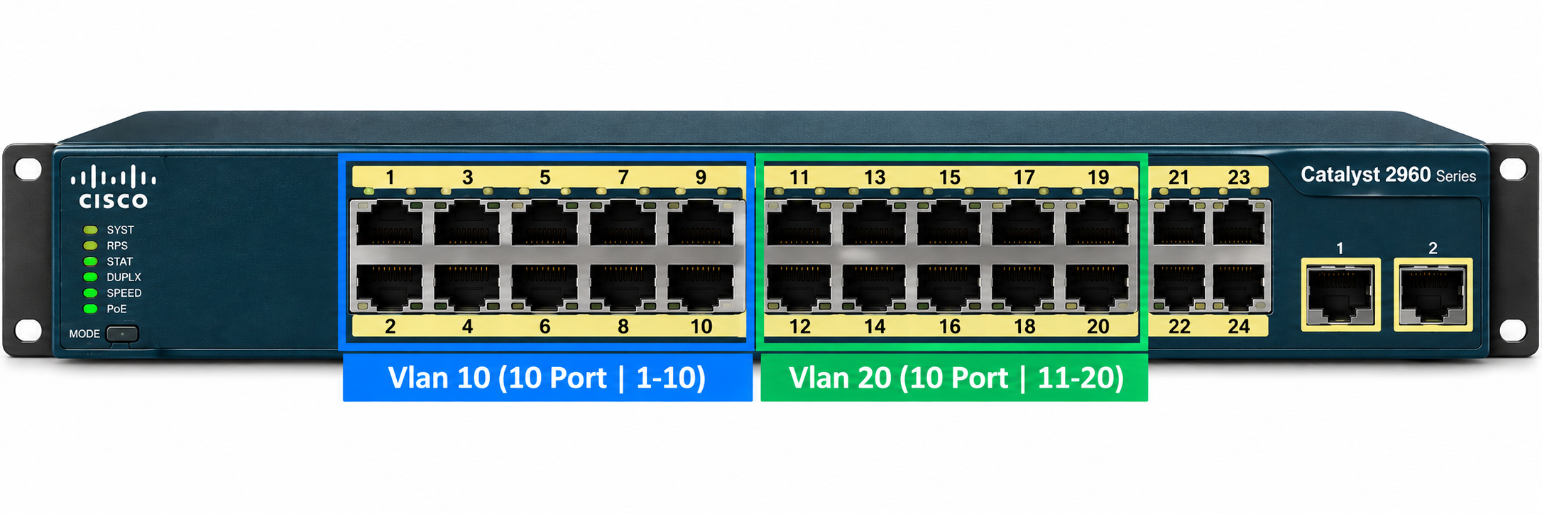
Floor 1 has the IT and IK departments. I assign the fastEthernet 0/1-10 ports to VLAN 10 for IT and the fastEthernet 0/11-20 ports to VLAN 20 for IK.
enable
configure terminal
interface range fastEthernet 0/1-10
 switchport mode access
 switchport access vlan 10
 exit
interface range fastEthernet 0/11-20
 switchport mode access
 switchport access vlan 20
 end
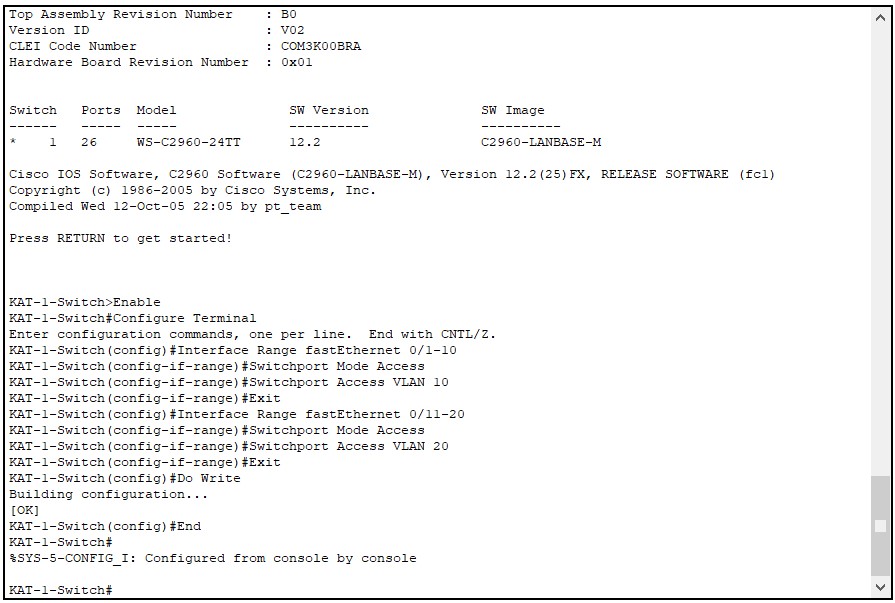
Step 23 - Checking the Port Assignments
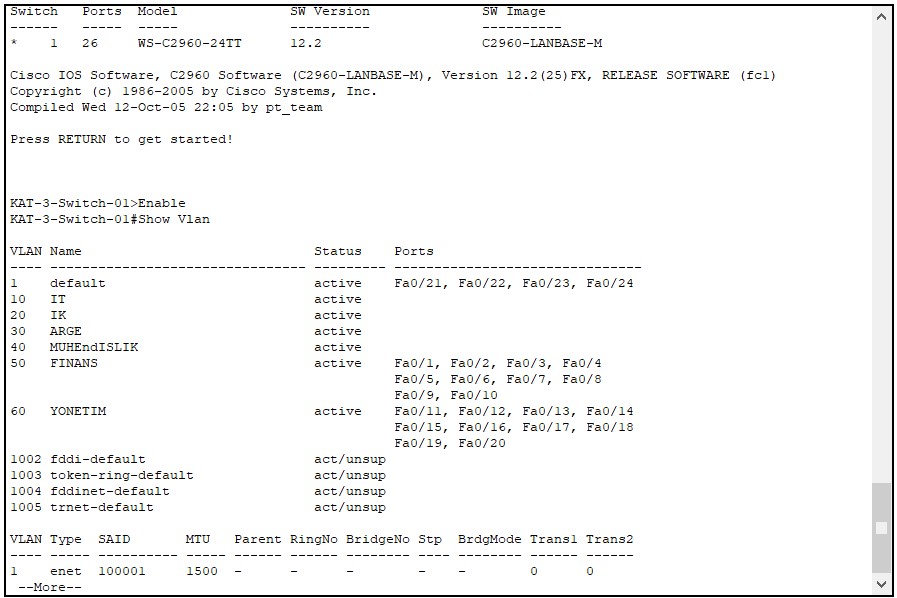
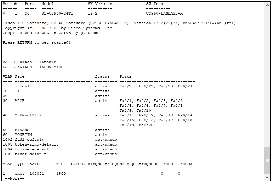
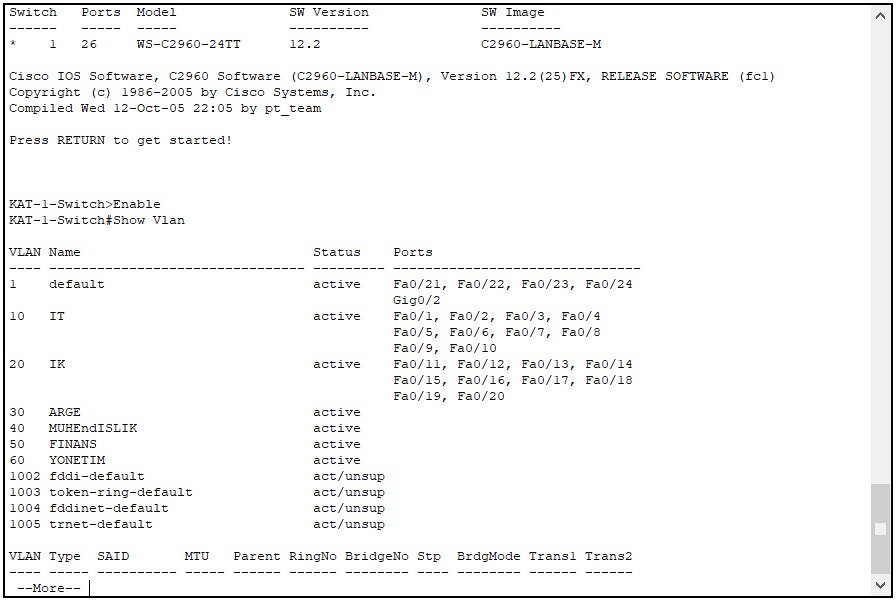
After I complete the port assignments, I run the Show Vlan Brief command on each floor switch and check that the VLANs are assigned to the relevant ports.
VLANs assigned to the switch ports on KAT-3-Switch-01:
VLANs assigned to the switch ports on KAT-2-Switch-01:
VLANs assigned to the switch ports on KAT-1-Switch-01:
Checkpoint
On each switch, Fa0/1-10 must appear in the port list of the first department VLAN and Fa0/11-20 in the port list of the second department VLAN. Trunk ports do not appear in the show vlan list.
11- SVI, IP Routing and DHCP Relay Configuration
Each department is now in its own VLAN, but the clients cannot obtain an IP address yet and the VLANs cannot reach each other. In this section, I create a Switch Virtual Interface (SVI) for each VLAN on the L3 switch and assign it an IP address, enable routing between the VLANs with ip routing, and forward DHCP requests to the DHCP server with ip helper-address. First, I explain how the DHCP server assigns IP addresses to the other VLANs although it is in a single VLAN.
How Does a DHCP Server in a Single VLAN Assign IP Addresses to Other VLANs?
The port that the DHCP server is connected to does not need to be a trunk. The DHCP server is connected to an access port in VLAN 10, and its IP address is also from the IP block of VLAN 10. Trunk ports are used on links between switches or in scenarios such as Router-on-a-Stick. Making the server port a trunk requires VLAN tagging support on the network adapter of the server and a separate IP configuration for each VLAN, and it provides no benefit in this scenario.
The DHCP relay agent on the L3 switch allows the clients in the other VLANs to obtain an IP address from this server. When ip helper-address is entered on an SVI, Cisco IOS enables the relay agent on that interface. By default, this command forwards the UDP broadcasts of the TFTP, DNS, Time, NetBIOS, TACACS and IEN-116 services, as well as DHCP/BootP, to the specified address. This list can be extended by UDP port number. The process by which a client in VLAN 30 obtains an IP address proceeds in this order:
1. The client sends a DHCP Discover message to obtain an IP address. This message is a broadcast at Layer 2.
2. The broadcast travels only within VLAN 30, because the broadcast of a VLAN does not pass to the other VLANs. Because the DHCP server is in VLAN 10, the message cannot reach the server directly.
3. ip helper-address 10.10.10.100 is defined on the VLAN 30 SVI on the L3 switch. This address belongs to the DHCP server in VLAN 10.
4. The L3 switch receives the broadcast message of the client and, instead of forwarding the same packet, creates a new DHCP message. In the giaddr (Gateway IP Address) field of this message, it writes the IP address of the interface on which the request arrived, which is 10.10.30.254, the address of the VLAN 30 SVI, and it sends the message to the DHCP server as IP unicast.
5. The DHCP server checks the address in the giaddr field and understands that the request came from the 10.10.30.0/24 network. It selects an address from the scope of this network and sends the DHCP Offer message to the L3 switch.
6. The L3 switch forwards the Offer message to the client in VLAN 30. The client requests this offer with a DHCP Request, and this message also reaches the server by the same path.
7. The DHCP server confirms the address assignment with a DHCP ACK, and the L3 switch forwards this message to the client.
8. The client has now obtained an IP address, a subnet mask and the default gateway information from a DHCP server outside its own VLAN.
Because the replies of the server go to another subnet, this flow works only if the VLAN 10 SVI address (10.10.10.254) is defined as the default gateway on the DHCP server.
Step 24 - Configuring the SVIs, IP Routing and DHCP Relay
I do the configuration on the L3 switch in 3 parts:
ip routing enables routing between the VLANs. It is entered once in global configuration mode. Without this command, the L3 switch does not route packets between the SVIs, and devices in different VLANs cannot communicate.
interface vlan and ip address create an SVI for each VLAN and assign it an IP address. These addresses are the default gateway addresses of the clients in the relevant VLAN.
ip helper-address 10.10.10.100 enables DHCP relay on the SVIs of the VLANs that are not in the same subnet as the DHCP server. In this design, this line is entered only on the VLAN 20, 30, 40, 50 and 60 SVIs. Because the DHCP server is already in VLAN 10, relay is not needed under interface vlan 10.
enable
configure terminal
ip routing
interface vlan 10
 ip address 10.10.10.254 255.255.255.0
 exit
interface vlan 20
 ip address 10.10.20.254 255.255.255.0
 ip helper-address 10.10.10.100
 exit
interface vlan 30
 ip address 10.10.30.254 255.255.255.0
 ip helper-address 10.10.10.100
 exit
interface vlan 40
 ip address 10.10.40.254 255.255.255.0
 ip helper-address 10.10.10.100
 exit
interface vlan 50
 ip address 10.10.50.254 255.255.255.0
 ip helper-address 10.10.10.100
 exit
interface vlan 60
 ip address 10.10.60.254 255.255.255.0
 ip helper-address 10.10.10.100
 end
In the screenshot below, the ip helper-address line also appears under interface vlan 10. This line is not required for relay and is not included in the configuration above.
After ip routing is enabled, all VLANs can reach each other. If access to VLANs such as FINANS must be restricted, ACLs must be applied to the SVIs.
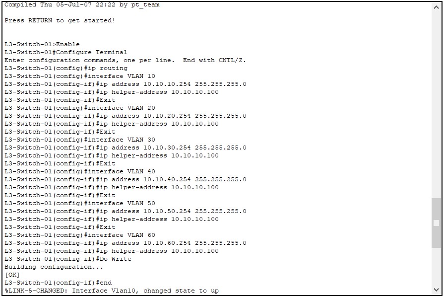
After this configuration, I create a separate scope for each VLAN on the DHCP server. The address range of each scope is selected from the subnet of its own VLAN, and the SVI address of that VLAN is given as the Router (default gateway) option. For requests that arrive through the relay, the server checks the SVI address in the giaddr field and decides which scope to assign an address from. In this way, the clients obtain IP addresses from the scopes that belong to their own VLAN IDs.
This article covered how the VLAN structure divides a single switch infrastructure into logical segments, how each segment forms its own broadcast domain and limits flooded traffic, and how the data, default, native, management and voice roles differ from each other. The configuration was then applied step by step in Cisco Packet Tracer, in a network topology built with 1 Layer 3 switch and 3 floor switches.
802.1Q trunk links, which carry the traffic of different segments over a single physical link, were established between the floor switches and the backbone switch. The segment definitions were distributed from the server to the clients with VTP. The role of the domain name, the password and the configuration revision number in this distribution was also explained.
Inter-VLAN Routing was provided with the SVIs created for each segment on the Layer 3 switch. With the DHCP relay agent configuration, the DHCP server located in a single segment was able to assign IP addresses to the other departments as well.
A correctly designed structure keeps broadcast traffic in the segment where it originates and separates the departments from each other at Layer 2. Adding a switch with a high revision number to the domain can delete all VLAN information. When routing is enabled, access between segments is also permitted. For these 2 reasons, the VTP plan and the ACL policy must be considered together at the design stage.
I hope you find it useful...
Feel free to share your thoughts and questions about this article in the comments below. Every contribution helps the content reach more people and makes for a more useful discussion.