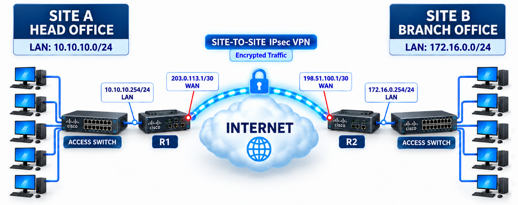
A site-to-site IPsec VPN connects the local networks of 2 geographically separate locations through an encrypted tunnel over an untrusted medium such as the Internet. Instead of a dedicated connection such as a leased line or Multiprotocol Label Switching (MPLS) between the head office and the branch, the Internet connections of both sides are used, and the tunnel between the 2 routers ensures that traffic between the locations cannot be read or modified from outside.
In this structure, the clients do not use any VPN software. The routers at the edge of the network perform the encryption and decryption. When a client sends a packet to an address at the remote location, the packet first reaches its own default gateway address. The router recognises that this packet is traffic that must pass through the tunnel, encrypts it with Encapsulating Security Payload (ESP), places it inside a new outer IP header and sends it to the public IP address of the remote router. The remote side decrypts the packet and delivers it to its own local network.
The tunnel is established through a 2-stage negotiation. In IKE Phase 1, the 2 routers authenticate each other and create a secure channel that protects the negotiation between them. In IKE Phase 2, the IPsec Security Associations that carry the actual user traffic are agreed over this channel. An access list determines which traffic is encrypted, and the crypto map determines with whom and with which parameters it is encrypted.
In this article, the routers of 2 locations are given their IP configuration in Cisco Packet Tracer, and then a Site-to-Site IPsec VPN is established between the 2 routers. After the configuration, the tunnel is verified in 3 stages. First, the path of the packet between the 2 locations is followed in Simulation Mode, then a ping test is run between the clients, and finally the state of the tunnel is checked with the show crypto ipsec sa output.
Topology and Addressing Plan
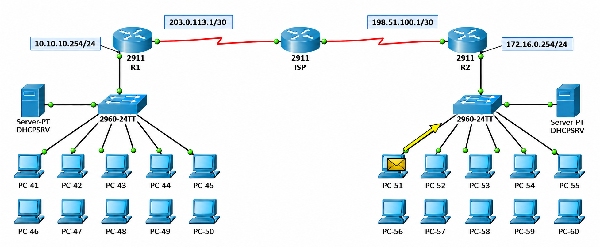
The scenario has a head office and a branch. The head office, named Site A, uses the 10.10.10.0/24 network, and the branch, named Site B, uses the 172.16.0.0/24 network. At both locations, the clients connect to the router through an access switch. Router-01 has the address 10.10.10.254 on the LAN side and 203.0.113.1/30 on the WAN side, and Router-02 has the address 172.16.0.254 on the LAN side and 198.51.100.1/30 on the WAN side. Traffic between the 2 locations is carried over the Internet through the encrypted tunnel between Router-01 and Router-02.
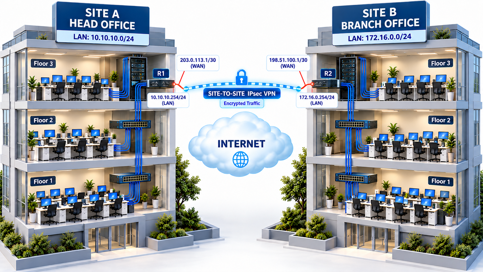
When the same structure is considered in terms of physical layout, the clients spread across the floors of both buildings connect through the floor switches to the router at the Internet edge of the building. Whichever floor the users are on, their traffic to the remote location is encrypted on the router of their own building and enters the tunnel.
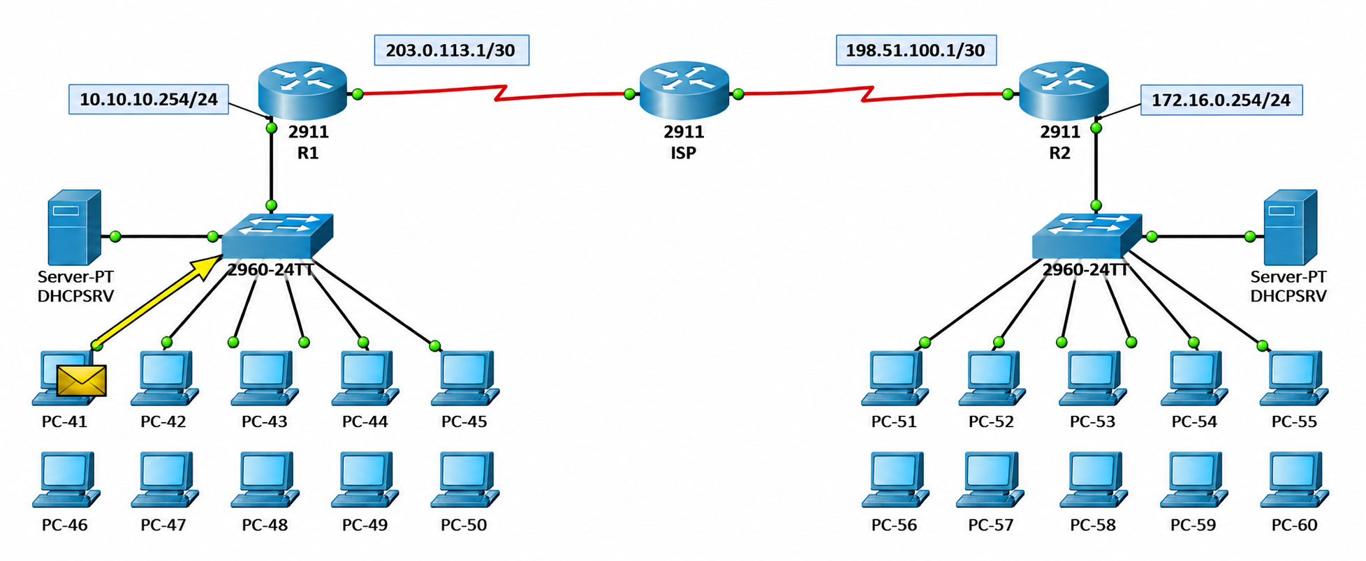
In the Packet Tracer equivalent, Router-01 is on the Site A side and Router-02 is on the Site B side. Each location has 1 2960 switch, 1 DHCP server and 10 clients. The 2 routers reach each other over serial links through an ISP router that represents the Internet.
The ISP router knows only the IP addresses of the WAN links and has no route information for the 10.10.10.0/24 and 172.16.0.0/24 networks. Because the real Internet does not carry the private IP blocks of companies either, this matches real conditions exactly. The tunnel will be the only way for traffic between the locations to reach the other side.
The hostname of the Site A router is defined as Router-01, and the hostname of the Site B router is defined as Router-02. On both routers, the GigabitEthernet0/1 interface is connected to the LAN side and the Serial0/0/0 interface is connected to the WAN side that faces the ISP. Because the WAN connections are point-to-point links with 2 ends, they are addressed with a /30 subnet. The table below lists the interface, IP address and role information of the routers.
|
Router |
Interface |
IP Address |
Role |
|
Router-01 |
GigabitEthernet0/1 |
10.10.10.254/24 |
Site A LAN gateway, inside |
|
Router-01 |
Serial0/0/0 |
203.0.113.1/30 |
Site A WAN, outside |
|
Router-02 |
GigabitEthernet0/1 |
172.16.0.254/24 |
Site B LAN gateway, inside |
|
Router-02 |
Serial0/0/0 |
198.51.100.1/30 |
Site B WAN, outside |
To use the crypto commands on a 2911 router, the securityk9 Technology Package licence must be active.
Router-01 Configuration
Router-01 is the device at the Internet edge of Site A, and it forms the head office end of the tunnel. The configuration on this router proceeds in 5 steps.
|
Step |
Operation |
Structure Used |
|
1 |
Assigning IP addresses to the LAN and WAN interfaces and defining the default route that points to the ISP |
Interface, default route |
|
2 |
Determining the traffic to be encrypted |
Interesting traffic access list |
|
3 |
Defining the IKE Phase 1 parameters and peer authentication |
ISAKMP policy, pre-shared key |
|
4 |
Defining the IKE Phase 2 encryption parameters |
Transform set |
|
5 |
Combining all parts and applying them to the Serial0/0/0 interface |
Crypto map |
The router does not encrypt any traffic until the crypto map is applied to the interface. For this reason, the tunnel does not become active before the last step is completed.
Interface and Default Route Configuration
In the first step, IP addresses are assigned to the LAN and WAN interfaces of Router-01. GigabitEthernet0/1 is the inside interface and the default gateway of the Site A clients. Serial0/0/0 is the outside interface that faces the ISP and forms the Router-01 end of the tunnel.
After the interfaces, a default route that points to the ISP is defined. This route has 2 functions. First, it allows Router-01 to reach the address 198.51.100.1, which is the remote peer. Second, it makes packets for the 172.16.0.0/24 network leave through Serial0/0/0. Because the crypto map will be applied to this interface, the traffic that must be encrypted has to be routed to this interface.
enable
configure terminal
interface g0/1
ip address 10.10.10.254 255.255.255.0
no shutdown
exit
interface s0/0/0
ip address 203.0.113.1 255.255.255.252
no shutdown
exit
ip route 0.0.0.0 0.0.0.0 203.0.113.2
Interesting Traffic Definition
The first part of the IPsec configuration is the extended access list that determines which traffic is encrypted. This access list is called interesting traffic. Here, the permit statement does not mean that the traffic is allowed. It means that the matching traffic is encrypted. Traffic that does not match continues with normal routing without entering the tunnel.
The access list on Router-01 defines the traffic whose source is 10.10.10.0/24 and whose destination is 172.16.0.0/24. Router-02 will have the exact reverse of the same definition. The access lists on the 2 sides must mirror each other. Otherwise, the proxy IDs do not match during Phase 2 and the IPsec SA is not created.
access-list 100 permit ip 10.10.10.0 0.0.0.255 172.16.0.0 0.0.0.255
IKE Phase 1 Configuration
Phase 1 is the stage in which the 2 routers authenticate each other. In this stage, the routers communicate over UDP 500 and establish a single ISAKMP SA (Internet Security Association and Key Management Protocol Security Association) between them. Both sides share this SA, and the Phase 2 negotiation runs over this secure channel.
For Phase 1 to succeed, the ISAKMP policies on the 2 sides must be compatible. The encryption, hash, authentication and Diffie-Hellman group values must be the same on both sides. The lifetime value does not have to be the same. The router that starts the tunnel, that is, the initiator, proposes its own policy values to the other side. The lifetime on the responder, which evaluates the proposal, must be less than or equal to the value that the initiator proposes. When this condition is met, the shorter lifetime is used. The policy number only determines which policy is tried first when there is more than 1 policy. The table below lists the parameters used and their roles.
|
Parameter |
Value |
Role |
|
encr |
aes |
Encryption algorithm of the Phase 1 channel |
|
hash |
sha |
Hash algorithm for the message integrity check |
|
authentication |
pre-share |
Peer authentication with a pre-shared key |
|
group |
2 |
1024-bit Diffie-Hellman group for key generation |
|
lifetime |
86400 |
Validity period of the ISAKMP SA in seconds |
After the policy is defined, the pre-shared key is set with the crypto isakmp key command. Because the key is bound to the IP address of the remote peer, Router-01 uses this key only in the negotiation with 198.51.100.1.
crypto isakmp policy 10
encr aes
hash sha
authentication pre-share
group 2
lifetime 86400
exit
crypto isakmp key cisco123 address 198.51.100.1
IKE Phase 2 Configuration
In Phase 2, the IPsec SAs that carry the actual user traffic are created. These SAs are unidirectional, and a separate SA is established for each direction. The transform set determines which protocol and algorithms these SAs use. The transform set named VPN-TS uses the ESP protocol with AES encryption and SHA HMAC integrity checking. The content of the transform set must match on both sides.
crypto ipsec transform-set VPN-TS esp-aes esp-sha-hmac
In real IOS, this command enters cfg-crypto-trans mode and mode tunnel is entered there. In the Packet Tracer version used in this lab, the command did not enter the sub-mode and the mode tunnel line returned an error. Tunnel mode is the default value in any case.
Crypto Map Definition and Application to the Interface
The crypto map is the structure that brings together the parts defined so far. It collects under a single entry which peer the tunnel is established with, which transform set is used and which traffic is encrypted. In entry 10 of the crypto map named VPN-MAP, the ipsec-isakmp keyword states that the keys are generated dynamically with IKE.
The crypto map does nothing by itself. It must be applied to the outside interface for the traffic to be encrypted. Every packet that leaves through Serial0/0/0 and matches access list 100 is encrypted at this point and sent to the peer.
crypto map VPN-MAP 10 ipsec-isakmp
set peer 198.51.100.1
set transform-set VPN-TS
match address 100
exit
interface s0/0/0
crypto map VPN-MAP
end
write memory
The complete configuration applied on Router-01 is listed below in step order.
Router-01> enable
Router-01# configure terminal
! Interface configuration
Router-01(config)# interface g0/1
Router-01(config-if)# ip address 10.10.10.254 255.255.255.0
Router-01(config-if)# no shutdown
Router-01(config-if)# exit

Router-01(config)# interface s0/0/0
Router-01(config-if)# ip address 203.0.113.1 255.255.255.252
Router-01(config-if)# no shutdown
Router-01(config-if)# exit

! Default route
Router-01(config)# ip route 0.0.0.0 0.0.0.0 203.0.113.2

! Interesting traffic
Router-01(config)# access-list 100 permit ip 10.10.10.0 0.0.0.255 172.16.0.0 0.0.0.255

! IKE Phase 1 (ISAKMP)
Router-01(config)# crypto isakmp policy 10
Router-01(config-isakmp)# encr aes
Router-01(config-isakmp)# hash sha
Router-01(config-isakmp)# authentication pre-share
Router-01(config-isakmp)# group 2
Router-01(config-isakmp)# lifetime 86400
Router-01(config-isakmp)# exit
Router-01(config)# crypto isakmp key cisco123 address 198.51.100.1

! IKE Phase 2 (IPsec)
Router-01(config)# crypto ipsec transform-set VPN-TS esp-aes esp-sha-hmac

! Crypto map
Router-01(config)# crypto map VPN-MAP 10 ipsec-isakmp
Router-01(config-crypto-map)# set peer 198.51.100.1
Router-01(config-crypto-map)# set transform-set VPN-TS
Router-01(config-crypto-map)# match address 100
Router-01(config-crypto-map)# exit

Router-01(config)# interface s0/0/0
Router-01(config-if)# crypto map VPN-MAP
Router-01(config-if)# end
Router-01# write memory
Router-02 Configuration
Router-02 is the device at the Internet edge of Site B, and it forms the branch end of the tunnel. The configuration steps follow the same order as on Router-01. The Phase 1 and Phase 2 parameters must be exactly the same on both sides. Otherwise, the tunnel is not established. The table below lists the values that differ between the 2 routers.
|
Configuration |
Router-01 |
Router-02 |
|
LAN interface (GigabitEthernet0/1) |
10.10.10.254/24 |
172.16.0.254/24 |
|
WAN interface (Serial0/0/0) |
203.0.113.1/30 |
198.51.100.1/30 |
|
Default route next hop |
203.0.113.2 |
198.51.100.2 |
|
Access list source / destination |
10.10.10.0/24 / 172.16.0.0/24 |
172.16.0.0/24 / 10.10.10.0/24 |
|
Pre-shared key peer address |
198.51.100.1 |
203.0.113.1 |
|
Crypto map set peer |
198.51.100.1 |
203.0.113.1 |
The ISAKMP policy, the transform set, the crypto map name and the pre-shared key value stay the same on both routers.
Interface and Default Route Configuration
The same logic applies on the Router-02 side. GigabitEthernet0/1 is the inside interface and the default gateway of the Site B clients, and Serial0/0/0 is the outside interface that forms the Router-02 end of the tunnel. The default route points to the address 198.51.100.2 on the ISP side.
enable
configure terminal
interface g0/1
ip address 172.16.0.254 255.255.255.0
no shutdown
exit
interface s0/0/0
ip address 198.51.100.1 255.255.255.252
no shutdown
exit
ip route 0.0.0.0 0.0.0.0 198.51.100.2
IPsec VPN Configuration
The IPsec configuration on Router-02 mirrors the configuration on Router-01. The source and destination are swapped in the access list, and the pre-shared key and set peer values point to 203.0.113.1, which is the WAN address of Router-01. The ISAKMP policy, transform set and crypto map content stay the same as on Router-01.
access-list 100 permit ip 172.16.0.0 0.0.0.255 10.10.10.0 0.0.0.255
crypto isakmp policy 10
encr aes
hash sha
authentication pre-share
group 2
lifetime 86400
exit
crypto isakmp key cisco123 address 203.0.113.1
crypto ipsec transform-set VPN-TS esp-aes esp-sha-hmac
crypto map VPN-MAP 10 ipsec-isakmp
set peer 203.0.113.1
set transform-set VPN-TS
match address 100
exit
interface s0/0/0
crypto map VPN-MAP
end
write memory
The complete configuration applied on Router-02 is listed below in step order.
Router-02> enable
Router-02# configure terminal
! Interface configuration
Router-02(config)# interface g0/1
Router-02(config-if)# ip address 172.16.0.254 255.255.255.0
Router-02(config-if)# no shutdown
Router-02(config-if)# exit

Router-02(config)# interface s0/0/0
Router-02(config-if)# ip address 198.51.100.1 255.255.255.252
Router-02(config-if)# no shutdown
Router-02(config-if)# exit

! Default route
Router-02(config)# ip route 0.0.0.0 0.0.0.0 198.51.100.2

! Interesting traffic
Router-02(config)# access-list 100 permit ip 172.16.0.0 0.0.0.255 10.10.10.0 0.0.0.255

! IKE Phase 1 (ISAKMP)
Router-02(config)# crypto isakmp policy 10
Router-02(config-isakmp)# encr aes
Router-02(config-isakmp)# hash sha
Router-02(config-isakmp)# authentication pre-share
Router-02(config-isakmp)# group 2
Router-02(config-isakmp)# lifetime 86400
Router-02(config-isakmp)# exit
Router-02(config)# crypto isakmp key cisco123 address 203.0.113.1

! IKE Phase 2 (IPsec)
Router-02(config)# crypto ipsec transform-set VPN-TS esp-aes esp-sha-hmac

! Crypto map
Router-02(config)# crypto map VPN-MAP 10 ipsec-isakmp
Router-02(config-crypto-map)# set peer 203.0.113.1
Router-02(config-crypto-map)# set transform-set VPN-TS
Router-02(config-crypto-map)# match address 100
Router-02(config-crypto-map)# exit

Router-02(config)# interface s0/0/0
Router-02(config-if)# crypto map VPN-MAP
Router-02(config-if)# end
Router-02# write memory
group 2 is for lab purposes and must not be used in a production environment. In production, strong Diffie-Hellman or ECDH groups, SHA-256 or stronger integrity algorithms and, if possible, IKEv2 should be preferred, and the pre-shared key must be impossible to guess. AES-128 and AES-256 can be used according to the security requirement.
Verifying the Tunnel
Path of the Packet in Simulation Mode
A crypto map based IPsec tunnel is not established at the moment the configuration is completed. The tunnel is triggered when the first packet that matches the access list reaches the router. Simulation Mode in Packet Tracer is used to see how the packet is carried between the 2 locations. The ICMP packet sent from PC-41 at Site A to PC-51 at Site B is advanced step by step and followed on the network. In the first step, the packet leaves PC-41 and goes to the Site A switch.
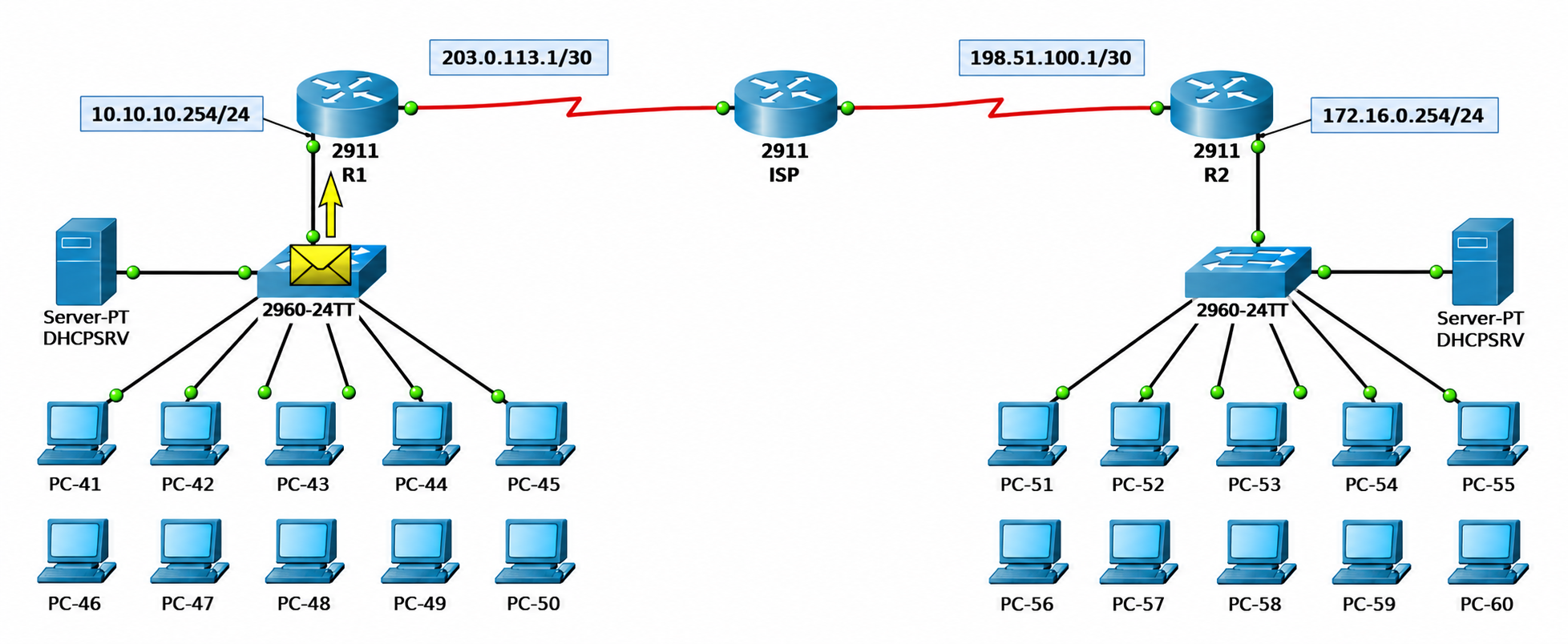
Because the destination address is on a different network, the switch forwards the packet to Router-01, which is the default gateway of PC-41.
The packet that reaches Router-01 has its source in the 10.10.10.0/24 network and its destination in the 172.16.0.0/24 network, so it matches access list 100. Router-01 routes the packet to Serial0/0/0 through the default route, the crypto map applied to this interface takes effect, and the packet is encrypted with ESP and encapsulated again with an outer IP header from 203.0.113.1 to 198.51.100.1. The encrypted packet leaves for the ISP over the serial link.
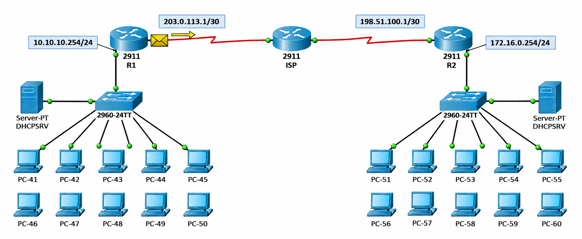
The ISP router sees only the outer IP header of the packet, and because it is directly connected to the address 198.51.100.1, it forwards the packet towards Router-02. Because the 10.10.10.0/24 and 172.16.0.0/24 addresses in the inner packet are encrypted, the fact that the ISP router does not know these networks does not prevent forwarding.
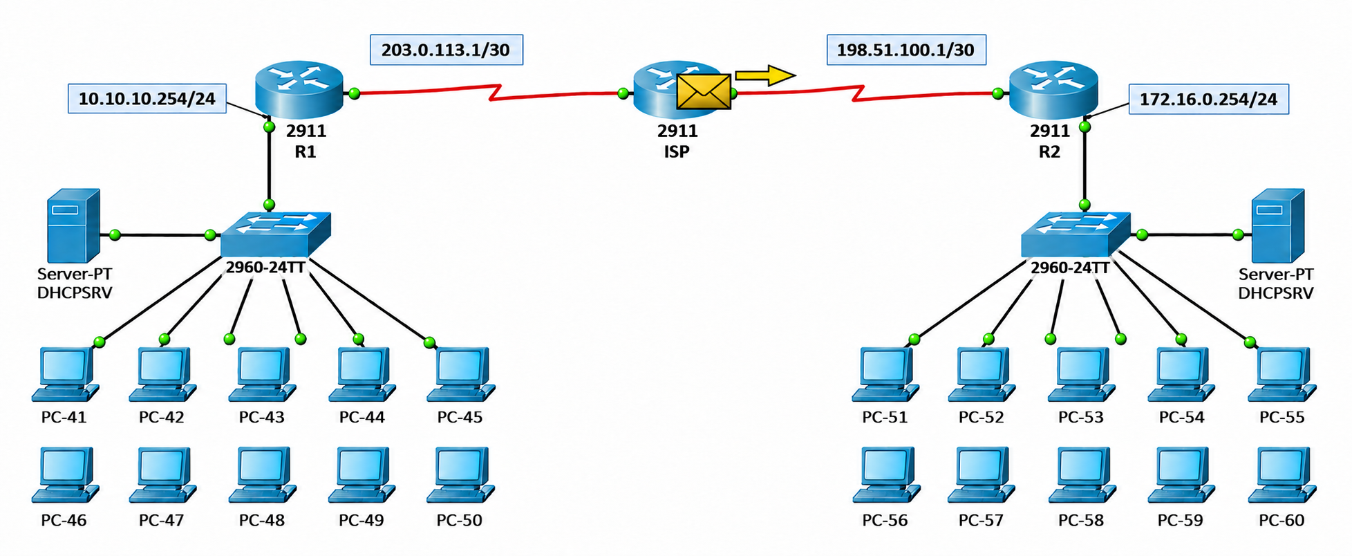
When the packet reaches Router-02, Router-02 decrypts it with its own IPsec SA and recovers the original ICMP packet. Because the destination is in the 172.16.0.0/24 network, the packet is forwarded to the Site B switch through GigabitEthernet0/1.
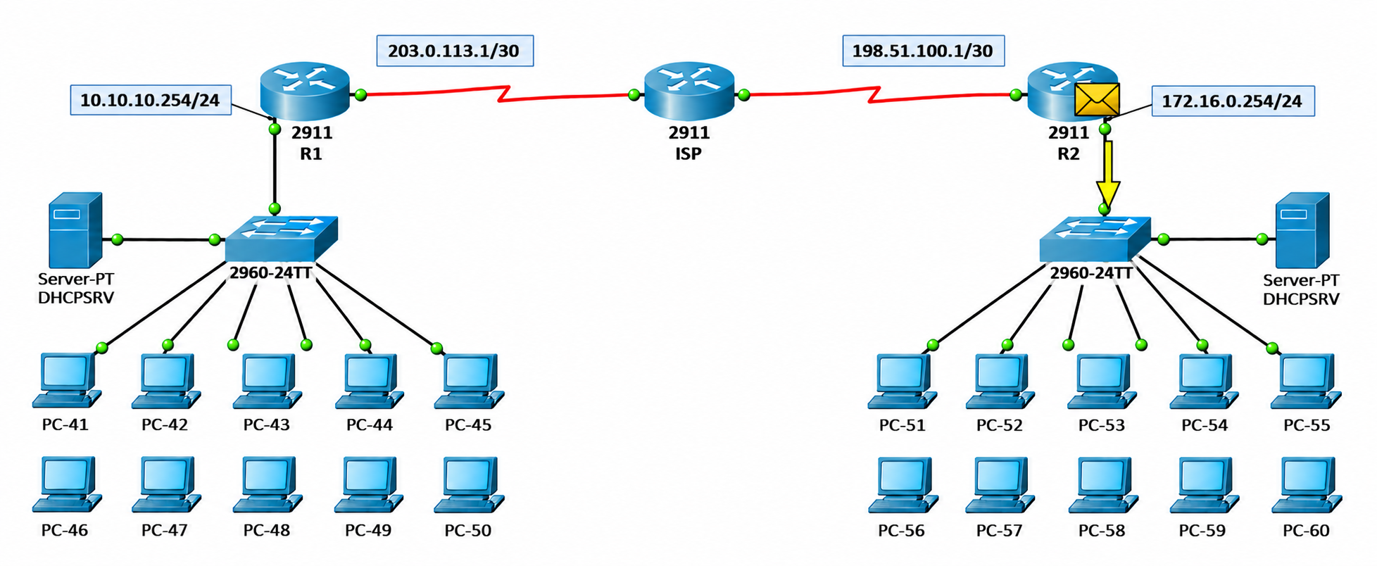
The Site B switch forwards the packet to the port where the destination client, PC-51, is connected.
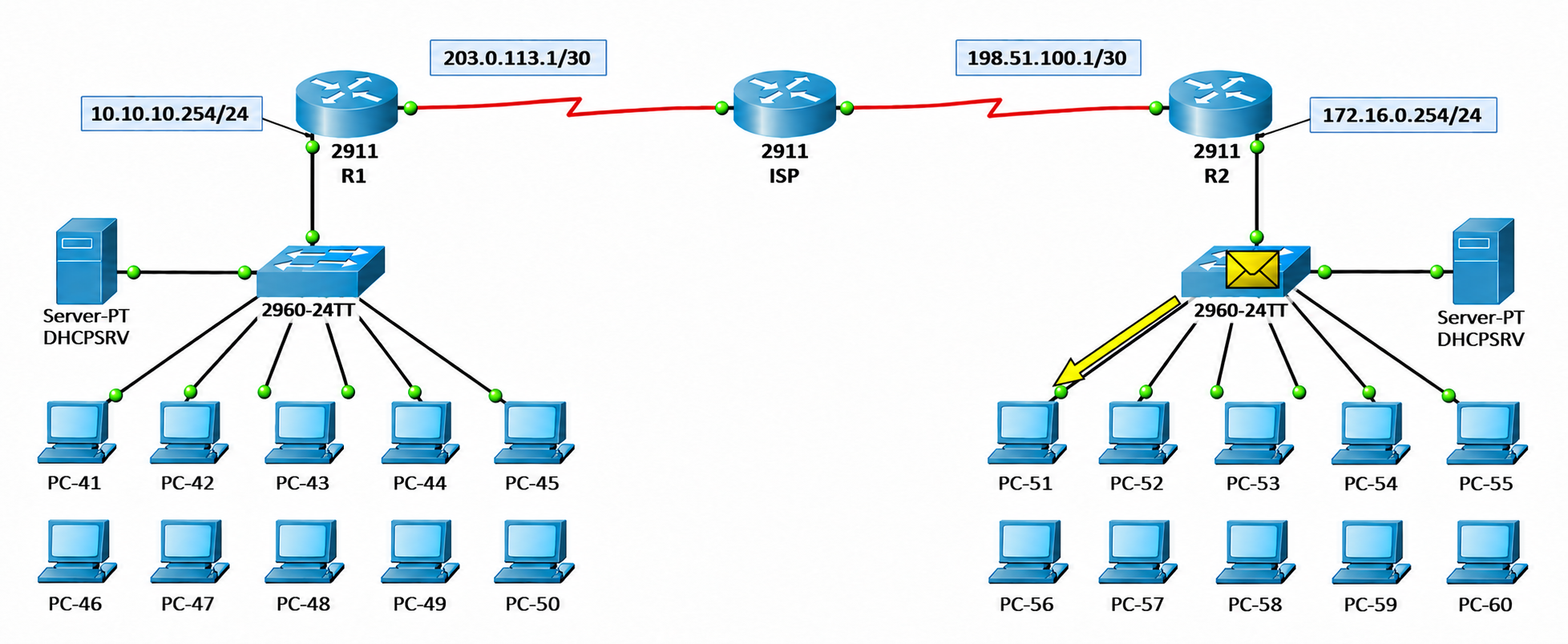
PC-51 receives the packet, creates its reply and sends it to the Site B switch. This reply follows the same path in the reverse direction. It is encrypted on Router-02, carried to Router-01 through the ISP, decrypted on Router-01 and delivered to PC-41.
Ping Test
The result of the flow seen in Simulation Mode is verified with the ping output in the Command Prompt on PC-41. PC-51 has received the IP address 172.16.0.12 through DHCP, and the Ping 172.16.0.12 command is run from PC-41.
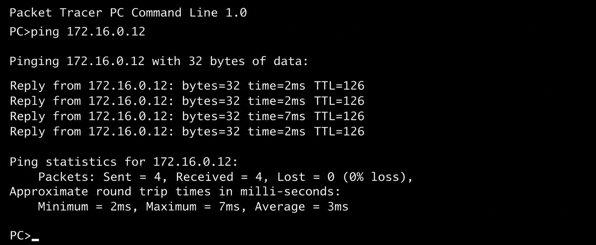
All 4 packets have received a reply. Because the tunnel was already established, no packet was dropped. On the first ping sent before the tunnel is established, it is expected that 1 or 2 packets time out while the negotiation is in progress.
The TTL=126 value in the replies shows how many routers the Echo Reply packet that reaches PC-41 passed through on the return path. To interpret this value correctly, you need to know that a packet in IPsec tunnel mode has 2 separate IP headers. The inner IP header belongs to the original packet between PC-51 and PC-41. The outer IP header is the header that Router-02 adds during ESP encapsulation and that is carried between 198.51.100.1 and 203.0.113.1. The TTL values of the 2 headers are independent of each other.
PC-51 sends the reply with 128 TTL. Because Router-02 forwards the inner packet, it reduces the inner TTL to 127, then it encrypts the packet and adds the outer header. The ISP routes the packet only by the outer header and reduces only the TTL value of the outer header. Because the inner header is encrypted inside the ESP payload, the ISP cannot read or change it. Router-01 decapsulates the packet and reduces the inner TTL to 126 when it forwards the inner packet to the LAN.
Echo Reply: PC-51 (172.16.0.12) -> PC-41

PC-51      sends               inner TTL = 128
Router-02  Forward + Encrypt   inner TTL = 127   outer header is added
ISP        by outer header     inner TTL = 127   only the outer TTL decreases
Router-01  Decrypt + Forward   inner TTL = 126   outer header is removed
PC-41      receives            TTL=126
In short, only Router-02 and Router-01, which route the inner packet, reduce the inner TTL. The ISP is not counted as a hop inside the tunnel. However, although the TTL value shows that the packet is carried inside the tunnel, it is not proof of encryption. The fact that encryption really takes place is verified in the next step with the encrypt and decrypt counters in the show crypto ipsec sa output.
Tunnel Check with show crypto ipsec sa
The state of the tunnel is examined with the show crypto ipsec sa command. The presence of IPsec SAs in this output shows that Phase 2, and therefore Phase 1 before it, completed successfully. Because a separate SA is created for each direction in Phase 2, the command is run on both routers. The command is run on Router-01 first.
show crypto ipsec sa
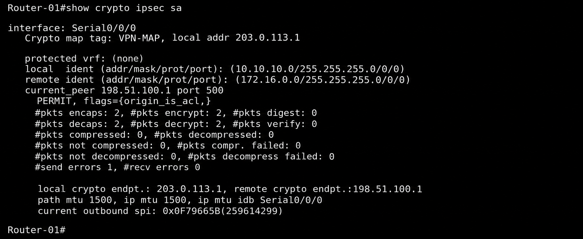
The table below lists the significant fields in the output and their values on Router-01.
|
Field |
Router-01 Value |
Meaning |
|
local ident / remote ident |
10.10.10.0/24 and 172.16.0.0/24 |
Networks that come from the access list and are protected by the tunnel |
|
current_peer |
198.51.100.1 port 500 |
Remote end of the tunnel and the IKE port |
|
#pkts encaps / Encrypt |
2 / 2 |
Number of packets encrypted and sent to the peer |
|
#pkts decaps / Decrypt |
2 / 2 |
Number of packets received from the peer and decrypted |
|
#send errors / #recv errors |
1 / 0 |
Number of errors counted on the IPsec send and receive sides |
|
local / remote crypto endpt. |
203.0.113.1 and 198.51.100.1 |
WAN and peer IP addresses at the 2 ends of the tunnel |
|
current Outbound spi |
0x0F79665B |
Identifier of the IPsec SA that carries the outbound traffic |
IPsec SAs are unidirectional. For this reason, 1 inbound and 1 outbound SA are created for each tunnel, and each of them is identified by its SPI value. The outbound traffic of Router-01 is encrypted with the SA that has the 0x0F79665B SPI value. When the same command is run on Router-02, the local ident and remote ident values are the exact reverse of Router-01, and a different SPI value, 0x33BC1438, is used for the outbound traffic of Router-02.
show crypto ipsec sa
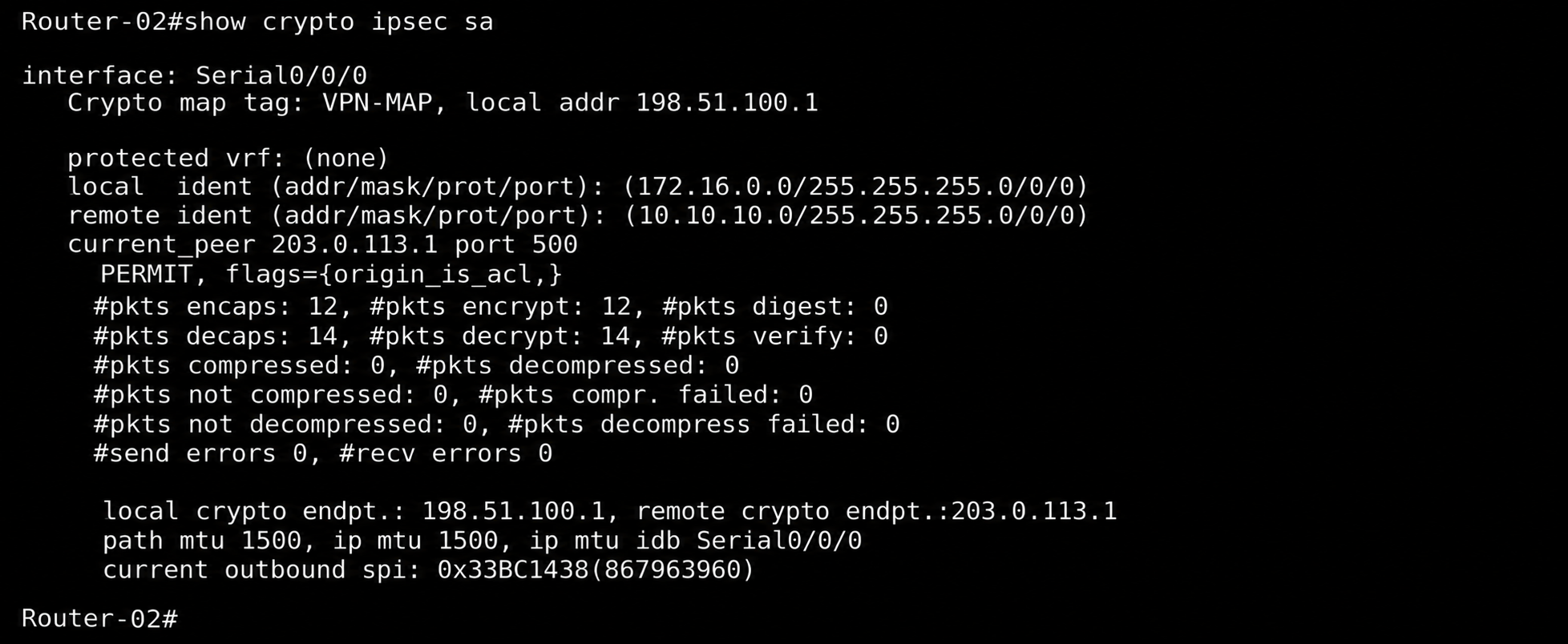
The presence of a separate SA for each direction and the increased encrypt and decrypt counters on both sides show that the traffic is encrypted and decrypted in both directions. The send errors value seen on Router-01 does not show the cause of the error by itself. If the value continues to increase, it must be examined with the detailed IPsec counters and debug outputs. The encaps and decaps counters in the Router-02 output are higher than on Router-01 because the output was taken later than on Router-01, after the ping traffic in between. The counters continue to increase with every packet that passes through the tunnel.
If the same IKEv1 and crypto map based structure is used in a real environment, the interesting traffic access list, peer, transform set, routing and crypto map logic applies in exactly the same way. However, the public IP addresses, the WAN interfaces, the routing and NAT design and the security parameters must be adapted to the environment. If a different architecture is preferred, such as IKEv2 or a VTI based route-based VPN, the configuration model also changes.
This article covered, end to end, the router-side configuration of the Site-to-Site IPsec VPN structure that connects a head office and a branch in Cisco Packet Tracer. The IP configuration of the inside and outside interfaces on Router-01 and Router-02 and the default route definition were covered as the foundation on which the IPsec configuration is built.
The IKE Phase 1 and IKE Phase 2 negotiation is at the centre of the configuration. In Phase 1, the peers authenticate each other with the ISAKMP policy and the pre-shared key, and a shared ISAKMP SA is established between the 2 routers. In Phase 2, the IPsec SAs that carry the user traffic are created, separately for each direction, with the ESP parameters set by the transform set. The requirement that the access list defined as interesting traffic is mirrored on the 2 sides is a decisive condition for the proxy ID match.
The crypto map combines the peer address, the transform set and the access list in a single structure, and as soon as it is applied to the outside interface, it starts to encrypt the matching traffic that leaves this interface. The flow followed in Simulation Mode shows concretely that the packet is encrypted on Router-01, carried through the ISP with only the outer IP header, and decrypted on Router-02 before it reaches the destination. When the same policy-based structure is moved to a real environment, the public IP, NAT and security parameters must be adapted to the environment.
In the verification stage, the ping output and the SAs, the encrypt and decrypt counters and the SPI values in the show crypto ipsec sa output were examined. The fact that traffic flows between the clients although the ISP router does not know the internal networks, together with the increase of the encryption counters on both routers, confirms that the IPsec tunnel traffic is carried over the encrypted channel.
I hope you find it useful...
Feel free to share your thoughts and questions about this article in the comments below. Every contribution helps the content reach more people and makes for a more useful discussion.