IP addresses and subnetting are critical for configuring a network correctly. In large-scale networks in particular, both concepts must be understood in depth in order to manage data traffic and optimise the addressing scheme.
An IP address is a numerical address that identifies a device on the network. This address allows devices to communicate with each other and ensures that data travels from the correct source to the correct destination. IPv4 addresses use a 32-bit address space, whereas IPv6 addresses, which offer a much larger addressing capacity, are 128 bits long. IPv4 addresses are written as 4 separate octets. The octets are separated by dots, and each one takes a value between 0 and 255.
For example, an IPv4 address such as 192.168.1.1 is the unique address of the device on the network. The network ID defines which network the address belongs to, and the host ID represents a specific device within that network. A subnet mask is used to make this distinction. The subnet mask determines which bits of the IP address are the network ID and which bits are the host ID. For example, the subnet mask 255.255.255.0 defines the first 24 bits (3 octets) of the IP address as the network ID, and the remaining 8 bits are the host ID.
Subnetting is the process of dividing an IP address range into smaller subnets. This process logically divides a large network into smaller subnets, which makes addressing more efficient and improves network performance. Each subnet (subnetwork) can hold a certain number of devices, and although all of these devices appear to belong to the same network, they are in fact in different subnets.
One of the biggest advantages of subnetting is the efficient use of IP addresses. For example, instead of managing all of its devices under a single network ID, a large organisation can use subnetting to create separate subnets for each department or location. Each subnet then has its own broadcast domain, and this isolates broadcast traffic.
Broadcast traffic means that a device sends data to all devices on the network at the same time. This type of traffic does not cause problems in small networks, but it can cause serious performance loss in large networks. The reason is that every device has to process the broadcast messages. As broadcast traffic increases, the devices on the network carry a higher load, and this has a negative effect on overall network performance.
Subnetting is an effective way to solve this problem. When the network is divided into small subnets with subnetting, each subnet has its own broadcast domain. A broadcast domain is the area to which broadcast traffic is limited. A broadcast sent by a device reaches only the devices in that subnet and does not spread to other subnets. Unnecessary broadcast traffic is therefore prevented in large networks. This improves network performance and allows the data traffic between devices to be managed more efficiently.
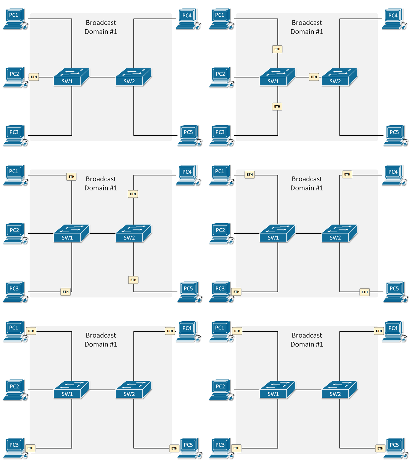
In this design, a packet sent from PC2 reaches all devices. This shows that all devices are in the same subnet and belong to a single broadcast domain. Because all devices are configured with the same subnet mask, broadcast messages spread to every device on the network.
Switches forward incoming broadcast messages to all of their ports without blocking them. For this reason, an ARP request or any other broadcast message sent from PC2 reaches all other devices, such as PC1, PC3, PC4 and PC5 . Because all devices are in the same broadcast domain, packets move freely.
This design is simple and practical for a small network, but as the number of devices increases, broadcast traffic can have a negative effect on network performance. In addition, because there is no security isolation between devices in the same subnet, potential vulnerabilities can affect the whole network. This type of design allows broadcast traffic to move without any limit, and the traffic cannot be managed or isolated.
To give another example, a subnet with the subnet mask 255.255.255.0 can contain 254 devices. The broadcast domain of this subnet is limited to these 254 devices. However, when the network is divided into smaller subnets, each subnet contains fewer devices and broadcast traffic is limited to those devices. Devices are therefore not exposed to unnecessary broadcast traffic, and the data flow on the network is more orderly.
Creating subnets is a critical task for limiting the broadcast traffic on a network and for providing performance and order. Devices in the same broadcast domain are exposed to unnecessary traffic, whereas subnets divide this traffic into smaller groups and devices receive only the traffic that concerns them. Unnecessary broadcast traffic on the network is therefore reduced to a minimum and the data flow becomes more efficient.
Another important advantage of subnets is that they provide security isolation. Because devices in the same subnet can communicate directly, security risks can increase, but subnets can limit this communication and reduce the effect of potential vulnerabilities. When the network is divided into smaller subnets, performance problems are prevented and security is improved. This makes it possible to manage and isolate the traffic on the network.
Subnetting and Security
Subnetting is not used only to use IP addresses efficiently or to make traffic management easier. It is also used as a strategic tool for security. Dividing the network into subnets provides both horizontal and vertical isolation. This isolation is an excellent method for limiting the effect of an attack and for giving critical systems better protection.
Suppose you are designing a network in a data centre that contains both user devices and servers. Isolating the subnet that contains the user devices from the subnet that contains the servers does not only improve performance. It also reduces the attack surface. If an attack occurs, the probability that it spreads to the other subnets is greatly reduced.
Defining security policies for specific subnets makes firewall rules more flexible and more targeted. For example, allowing only the traffic from a specific subnet to reach a database server makes unauthorised access almost impossible. In the same way, by restricting inbound traffic from outside to the user subnet, you can block attacks and also filter unnecessary traffic that has a negative effect on the user experience.
Subnetting also makes it easier to analyse logs and security events. In a correctly configured network, the subnet that an attack originates from can be identified very quickly. This shortens response times and allows threats to be isolated more quickly.
It is correct to say that subnetting is a critical tool not only for addressing but also for improving security. With every step you take to provide security, it does not take long to see the advantage that this configuration gives you.
IP Addressing
IP addressing is used in accordance with the routing layer (layer 3) of the TCP/IP protocol suite. IP addresses in IPv4 are 32 bits long. To make them easy to write and display, these numbers are divided into 4 separate parts of 8 bits each. Each of these parts is called an octet. We write and read IP addresses in decimal (base 10) notation because it is easy to write and read, but computers use binary (base 2) notation when they interpret them.
Numbers written in decimal notation are obtained from the total value of the bits in binary. Each octet consists of 8 bits, and each bit can take the value 0 or 1. When all bits are 1, the sum of the decimal equivalents of these bits is 255 at most, which is the highest value an octet can take. The 1 values also have mathematical equivalents, and these equivalents add up to totals. These totals give us values such as the IP address or the subnet mask. To explain this logic a little further, we have an IP address in the decimal number system, divided into 4 separate octets, with no values assigned yet. Let us look at the binary equivalents of this decimal IP address.
|
1st Octet |
2nd Octet |
3rd Octet |
4th Octet |
|
Decimal |
Decimal |
Decimal |
Decimal |
|
0 |
0 |
0 |
0 |
|
Binary |
Binary |
Binary |
Binary |
|
00000000 |
00000000 |
00000000 |
00000000 |
I will take the 1st octet of the binary equivalent and, on the 00000000. part, assign 1 values to the 0 values to go up to the upper limit of 255 . To do this, I will use the 2n formula, and when I move through the 2n formula from 20 to 27, I will have gone from 1 up to the upper value of 128.
Each decimal value in the range 1-128 corresponds to a binary value of 1. Conversely, we can also say that each binary value of 1 corresponds to a decimal value between 1 and 128. The sum of the decimal equivalents of all binary 1 values in an octet gives the IP address number in that octet. Each power of 2 gives us a binary value of 1. Each binary value of 1 corresponds to 1 bit.
|
1st Octet |
|
0 bit |
0 bit |
0 bit |
0 bit |
0 bit |
0 bit |
0 bit |
0 bit |
|
27=128 |
26=64 |
25=32 |
24=16 |
23=8 |
22=4 |
21=2 |
20=1 |
|
Equivalent |
Equivalent |
Equivalent |
Equivalent |
Equivalent |
Equivalent |
Equivalent |
Equivalent |
|
1 bit |
1 bit |
1 bit |
1 bit |
1 bit |
1 bit |
1 bit |
1 bit |
In an 8-bit octet, each bit represents a power of 2. The numerical value of the octet is found by adding the equivalents of the bits that have the value 1. When all bits are 1, the sum of these values is 255, which is the highest value an octet can take.
The 1 values that replace the 0 values are the parts that we will add together, and this total gives us the numerical equivalent in the relevant octet of the relevant IP address. Accordingly, for example, the binary equivalent of the decimal IP address 192.168.20.10 is shown below.
|
1st Octet |
2nd Octet |
3rd Octet |
4th Octet |
|
192 |
168 |
20 |
10 |
11000000 |
10101000 |
00010100 |
00001010 |
|
(128+64=192) |
(128+32+8=168) |
(16+4=20) |
(8+2=10) |
Public IP Addresses & Private IP Addresses
The distinction between public IP addresses and private IP addresses is essential for the Internet to work in an orderly way and without problems. Because each public IP address is globally unique, communication on the Internet continues without conflicts. When you consider that billions of devices worldwide communicate through these addresses, it is not difficult to understand why this distinction is so critical.
With private IP addresses, the limited number of public IP addresses can be used efficiently. Because of this distinction, devices in different local networks (LAN) can use the same addresses, and the NAT mechanism gives these devices access to the Internet. This saves addresses and also improves local network security.
If there were no distinction such as public and private IP addresses, all devices would have to share a single address pool, and this would cause complete disorder. Because of the current structure, everything on the Internet works in a more orderly and more secure way. IP addresses are not only a technical detail. They are one of the most basic elements at the centre of the digital world. It is no exaggeration to say that this system is the foundation of modern communication.
⚡ 1- Public IP Addresses
Public IP addresses allow devices to communicate directly on WAN networks such as the Internet. The IPv4 protocol has approximately 232 = 4,294,967,296 addresses, and this address pool is divided into specific classes. Because public IP addresses are open to everyone, they must be globally unique. For this reason, dividing IP addresses into public and private is a critical step for preventing conflicts.
Public IP addresses are assigned by Internet service providers (ISPs). With these addresses, data sent from any point on the Internet can be delivered directly, because the location of the destination system can be determined. In other words, public IP addresses allow the destination to be identified clearly and uniquely in global routing.
Now let us look at the IPv4 address classes.
The IPv4 protocol divides the address space into 5 classes, A, B, C, D and E. Of these, classes A, B and C are the main classes used for host assignment. Class D is used only for multicast communication, and class E is reserved by the IETF for experimental purposes. The table below summarises the start and end IP range of each class.
|
IPv4 Address Class |
Start IP |
End IP |
|
Class A |
1.0.0.0 |
126.255.255.255 |
|
Class B |
128.0.0.0 |
191.255.255.255 |
|
Class C |
192.0.0.0 |
223.255.255.255 |
|
Class D |
224.0.0.0 |
239.255.255.255 |
|
Class E |
240.0.0.0 |
255.255.255.255 |
The 0.0.0.0/8 and 127.0.0.0/8 blocks, which appear within class A, are reserved for special purposes. For this reason, the usable class A range is defined as 1.0.0.0 – 126.255.255.255. 127.0.0.0/8 is reserved for loopback, 169.254.0.0/16 for APIPA (link-local) and 100.64.0.0/10 for CGNAT.
Class D: The Multicast Class
Class D IP addresses are in the range 224.0.0.0 to 239.255.255.255 and are used only for multicast communication. Multicast is a transmission model in which the same data is sent once from a single source and delivered to more than 1 receiver at the same time. This reduces the load on the streaming server, prevents network traffic from growing unnecessarily and uses resources efficiently.
Multicast IP addresses are never assigned permanently to a physical device, because these addresses represent the group formed by the devices that want to receive the same stream. The streaming server sends the content with a single multicast IP address as the destination. Devices that want to receive this stream send a request to join the group to the router on the network through the IGMP protocol. The router then forwards the stream only to the ports where the requesting devices are connected. No data is sent to devices that have not joined.
For example, an IPTV provider can define the stream of a channel on the multicast IP address 239.1.1.1. When the smart TV or set-top box in the user's home opens this channel, the device sends a request to join this stream through IGMP. The server sends the data only once, and the router replicates the data and forwards it only to the devices that have joined the stream.
In services such as IPTV, these multicast streams are routed within the backbone network of the ISP that provides the service, not on the public Internet. This makes it possible to deliver data to thousands of users at the same time with a single stream and minimum resources. This method is used heavily in scenarios such as IPTV live broadcasting, real-time data streaming and corporate content distribution.
Class E: The Reserved Pool
The IP addresses in the range 240.0.0.0 to 255.255.255.255 are called Class E in the IPv4 architecture, and this is not a block that can be assigned for general use. This range was reserved entirely for experimental purposes during the design of IPv4. Because IANA keeps it outside the assignable address pool, it is not distributed through the Regional Internet Registries (RIR).
These blocks are reserved for the development, testing and analysis of new protocols that may be needed in the future. Modern operating systems and network devices treat this range as invalid by default. Most routers do not include these blocks in routing, and an IP address from this range cannot be assigned to any interface. Even so, the range is still used in kernel-level tests, protocol simulations and virtual network labs. The IETF has never declared these address blocks deprecated. It has only defined them as a non-production range.
⚡ 2- Private IP Addresses
Private IP addresses are address blocks in the IPv4 addressing system that are defined for use only inside the internal network and are not routed by any router on the external network. Because the IPv4 address pool is limited, this structure is used both as a mechanism for saving addresses and as a segmentation tool that isolates internal networks from the outside world.
Private addresses do not have to be globally unique. The same blocks can therefore be reused in different networks without conflicts. This property gives great flexibility, especially in multi-layer environments such as virtualisation, container architectures and overlay solutions.
Network Address Translation (NAT) is used so that devices with private IP addresses can access the Internet. NAT allows many devices on the internal network to reach the Internet at the same time through a single public IP address, and it also prevents the internal address structure from being seen directly from outside. The actual security control is provided by the firewall. The firewall filters both outbound traffic and requests from outside according to the defined rules, and only permitted connections reach the internal network. NAT and the firewall work together to keep connectivity and to form a basic barrier against external threats.
The private IP ranges below are the IP blocks defined in RFC 1918 that are suitable for use in internal networks:
|
Private IP Class |
Start IP |
End IP |
|
Class A |
10.0.0.0 |
10.255.255.255 |
|
Class B |
172.16.0.0 |
172.31.255.255 |
|
Class C |
192.168.0.0 |
192.168.255.255 |
The Subnet Mask Concept
One of the most critical parts we meet when we learn the logic of IP addresses is the subnet mask. It is a 32-bit sequence that determines which part of an IP address belongs to the network and which part is assigned to devices. This structure, which consists of zeros and ones, is in fact the basis of all routing logic.
For example, the subnet mask value that comes with 192.168.1.0/24 is 255.255.255.0. This shows that the first 24 bits are the network part and the remaining 8 bits are reserved for hosts. In this case, a maximum of 254 devices can communicate within this block. Because 1 address is reserved as the network ID and another as the broadcast address, 254 usable IP addresses remain.
The subnet mask does not only separate IP addresses. It is also at the centre of dividing and managing the network. For example, when a mask such as 255.255.255.192 is used, the address block you have is divided into 4 parts and each part offers 62 usable IP addresses. You therefore do not have to use blocks that are wider than you need.
Apart from performance, this structure is also useful for security. Because a subnet is isolated from the others, only specific devices can communicate with each other. This forms a natural boundary against attacks. It is not always ideal for everything in the same network to be open to everything else. Keeping critical components such as servers, management devices or security systems in separate subnets is a serious advantage.
Choosing the subnet mask is one of the most strategic steps in the design process. A wrong mask blocks an environment that tries to grow later. A correctly chosen mask increases scalability and makes documentation easier. This structure gives you a clear map, especially when you manage more than 1 physical or logical area.
Although it looks simple on the surface, the subnet mask is one of the main structural parts of network architecture. When you use it correctly, everything works as it should. The subnet mask does not only bring routing and segmentation. It also brings the logic for calculating how many devices can be assigned an IP address. In the IP addressing system, the subnet mask has a critical function in determining both network and host addresses.
In the tables below, you can see the subnet mask information for each class and the number of devices that can be addressed, based on powers of 2.
Class A Subnet Mask
|
Subnet Mask |
Binary Notation |
CIDR |
Host Bits |
Number of Hosts |
|
255.0.0.0 |
11111111.00000000.00000000.00000000 |
/8 |
32-8=24 |
224 -2 = 16,777,214 |
|
254.0.0.0 |
11111110.00000000.00000000.00000000 |
/7 |
32-7=25 |
225 -2 = 33,554,430 |
|
252.0.0.0 |
11111100.00000000.00000000.00000000 |
/6 |
32-6=26 |
226 -2 = 67,108,862 |
|
248.0.0.0 |
11111000.00000000.00000000.00000000 |
/5 |
32-5=27 |
227 -2 = 134,217,726 |
|
240.0.0.0 |
11110000.00000000.00000000.00000000 |
/4 |
32-4=28 |
228 -2 = 268,435,454 |
|
224.0.0.0 |
11100000.00000000.00000000.00000000 |
/3 |
32-3=29 |
229 -2 = 536,870,910 |
|
192.0.0.0 |
11000000.00000000.00000000.00000000 |
/2 |
32-2=30 |
230 -2 = 1,073,741,822 |
|
128.0.0.0 |
10000000.00000000.00000000.00000000 |
/1 |
32-1=31 |
231 -2 = 2,147,483,646 |
Class B Subnet Mask
|
Subnet Mask |
Binary Notation |
CIDR |
Host Bits |
Number of Hosts |
|
255.255.0.0 |
11111111.11111111.00000000.00000000 |
/16 |
32-16=16 |
216 -2 = 65,534 |
|
255.254.0.0 |
11111111.11111110.00000000.00000000 |
/15 |
32-15=17 |
217 -2 = 131,070 |
|
255.252.0.0 |
11111111.11111100.00000000.00000000 |
/14 |
32-14=18 |
218 -2 = 262,142 |
|
255.248.0.0 |
11111111.11111000.00000000.00000000 |
/13 |
32-13=19 |
219 -2 = 524,286 |
|
255.240.0.0 |
11111111.11110000.00000000.00000000 |
/12 |
32-12=20 |
220 -2 = 1,048,574 |
|
255.224.0.0 |
11111111.11100000.00000000.00000000 |
/11 |
32-11=21 |
221 -2 = 2,097,150 |
|
255.192.0.0 |
11111111.11000000.00000000.00000000 |
/10 |
32-10=22 |
222 -2 = 4,194,302 |
|
255.128.0.0 |
11111111.10000000.00000000.00000000 |
/9 |
32-9=23 |
223 -2 = 8,388,606 |
Class C Subnet Mask
|
Subnet Mask |
Binary Notation |
CIDR |
Host Bits |
Number of Hosts |
|
255.255.255.0 |
11111111.11111111.11111111.00000000 |
/24 |
32-24=8 |
28 -2 = 254 |
|
255.255.254.0 |
11111111.11111111.11111110.00000000 |
/23 |
32-23=9 |
29 -2 = 510 |
|
255.255.252.0 |
11111111.11111111.11111100.00000000 |
/22 |
32-22=10 |
210 -2 = 1,022 |
|
255.255.248.0 |
11111111.11111111.11111000.00000000 |
/21 |
32-21=11 |
211 -2 = 2,046 |
|
255.255.240.0 |
11111111.11111111.11110000.00000000 |
/20 |
32-20=12 |
212 -2 = 4,094 |
|
255.255.224.0 |
11111111.11111111.11100000.00000000 |
/19 |
32-19=13 |
213 -2 = 8,190 |
|
255.255.192.0 |
11111111.11111111.11000000.00000000 |
/18 |
32-18=14 |
214 -2 = 16,382 |
|
255.255.128.0 |
11111111.11111111.10000000.00000000 |
/17 |
32-17=15 |
215 -2 = 32,766 |
What Is Classless Inter-Domain Routing (CIDR)?
CIDR is a term that appears very often in IP addressing. It stands for Classless Inter-Domain Routing, and it is an addressing method developed to divide networks in a more flexible way. CIDR removes the limits of the traditional class-based use of IP addresses, such as classes A, B and C, and allows us to control every IP block at bit level.
Notations such as /8, /16 or /24 that follow an IP address show how many bits of the subnet mask of that address we assign to the network part. For example, /24 indicates that the first 24 bits are the network part. The remaining 8 bits are reserved for hosts. This means that 28 - 2 = 254 usable IP addresses can be produced within that network. This is how CIDR notation gives a simplified form of the subnet mask.
As the tables show, the CIDR column shows how many bits of network space the subnet mask in that row represents. With this notation, a much shorter and more readable format is used instead of traditional decimal notations such as 255.255.255.0. In addition, this notation makes calculations faster in subnetting and improves readability considerably.
If you work with subnetting, CIDR notation will be a key tool for you. It does not only divide the network. Through this notation you can also see within seconds how many IP addresses can be defined in that network. As the number increases, the number of networks increases and the number of hosts decreases. As the number decreases, you get fewer networks that cover wider ranges.
When you look at a table, the CIDR field is in fact the mathematical summary of the whole structure. CIDR notation is the shortest way to understand how many bits belong to the network part and how many bits belong to the host part. For this reason, when you look at the tables, it is useful to pay attention not only to the numbers but also to the space these numbers give you in network design.
How many bits of network space a subnet mask corresponds to, and how the number of assignable IP addresses changes as a result, can often be confusing. Especially when you work with CIDR notation, it is important to see how large a difference each bit makes in the system.
The table below compares the effect of different subnet mask values on classes A, B and C, together with their CIDR equivalents and the number of assignable IP addresses. You can therefore see clearly, in technical terms, how much host space each subnet mask offers for each class.
|
Class |
255 |
254 |
252 |
248 |
240 |
224 |
192 |
128 |
|
A- |
8 |
7 |
6 |
5 |
4 |
3 |
2 |
1 |
|
B- |
16 |
15 |
14 |
13 |
12 |
11 |
10 |
9 |
|
C- |
24 |
23 |
22 |
21 |
20 |
19 |
18 |
17 |
|
Subnet Mask |
|
A- |
255.0.0.0 |
254.0.0.0 |
252.0.0.0 |
248.0.0.0 |
240.0.0.0 |
224.0.0.0 |
192.0.0.0 |
128.0.0.0 |
|
B- |
255.255.0.0 |
255.254.0.0 |
255.252.0.0 |
255.248.0.0 |
255.240.0.0 |
255.224.0.0 |
255.192.0.0 |
255.128.0.0 |
|
C- |
255.255.255.0 |
255.255.254.0 |
255.255.252.0 |
255.255.248.0 |
255.255.240.0 |
255.255.224.0 |
255.255.192.0 |
255.255.128.0 |
|
NUMBER OF ASSIGNABLE IP ADDRESSES |
|
A- |
16,777,214 |
33,554,430 |
67,108,862 |
134,217,726 |
268,435,454 |
536,870,910 |
1,073,741,822 |
2,147,483,646 |
|
B- |
65,534 |
131,070 |
262,142 |
524,286 |
1,048,574 |
2,097,150 |
4,194,302 |
8,388,606 |
|
C- |
254 |
510 |
1,022 |
2,046 |
4,094 |
8,190 |
16,382 |
32,766 |
Subnetting - Subnet Calculation
In IP addressing, you cannot always get an address block of exactly the size you need. If the block you have is too large, IP addresses are wasted. If it is too small, it is not enough. This is exactly where subnetting is used. By dividing an IP block into smaller parts that match the need, you gain efficiency and you can also manage your environment in a much more controlled way.
Subnetting is in fact done by changing the subnet mask. The more bits you move to the network part, the more subnets you produce. However, the number of usable IP addresses that remain in each subnet decreases at the same time. This is therefore a question of balance. How many parts will you divide the block into, and how many devices will each part contain?
👉 At this point, 2 basic formulas are used, the total number of networks and the total number of hosts:
✅ Total networks: It is calculated with the 2n formula by converting the 0 values in the relevant octet of the subnet mask into 1 values, taking powers of 2 from left to right.
✅ Total hosts: It is determined with the 2h–2 formula from the 0 bits that remain after the 1s in the subnet mask.
The good thing about this process is that it is based on a fully mathematical order. Because the division is done at bit level, you can produce as many subnetworks as you want. Each bit that you set to 1 gives you 2 times more networks. In the opposite direction, the remaining 0 bits tell you how many devices you can address.
Today, both large environments and the smallest test environments are shaped by this logic. If there are requirements such as security, broadcast traffic, access policies or segmentation, subnetting is unavoidable. A network where every device is open to all others on a single flat IP block is now preferred almost nowhere.
If you have an IP block and a target, the rest is only calculation. How many parts will it be divided into, how many devices are needed, where are the broadcast addresses, how are the subnet IDs calculated… These can be solved with a few logical rules. Now let us move on to the practice.
💡 Example 1
We have the IP 192.168.10.0 /24. The subnet mask of this IP is 255.255.255.0. When dividing it into subnetworks, I want, for example, to divide this IP address into 15 separate networks. In this case, the subnet mask value and host count information of my current IP address are as follows.
👉Current subnet mask: 255.255.255.0 (/24)
👉Current subnet mask in binary: 11111111.11111111.11111111.00000000
Because I want to divide the current subnet mask into 15 networks, I can work only on the 0 area in the 4th octet of my current subnet mask.
Accordingly, to find how many networks will be produced, the number of bits that replace the 0 values in binary is counted and calculated with the 2n formula. This operation is shown with a logic that moves from right to left, that is, from the low-order bit towards the high-order bit. The reason is that the main focus here is how many different combinations result.
|
Number of Bits (2n) |
Number of Networks Produced |
Binary Subnet Mask (4th Octet) |
Description |
|
21 |
2 |
10000000 |
1 bit for 2 networks |
|
22 |
4 |
11000000 |
2 bits for 4 networks |
|
23 |
8 |
11100000 |
3 bits for 8 networks |
|
24 |
16 |
11110000 |
4 bits for 16 networks (because 15 networks are required) |
However, the direction is reversed when you find the decimal equivalent of the subnet mask. When you determine which value the bits set to 1 in binary correspond to, you move from left to right, that is, from the high-order bit towards the low-order bits. The reason is that bit positions such as 128, 64, 32, 16... affect the value directly.
Accordingly, the binary value 11110000 in the 4th octet of the subnet mask gives 240 as the sum of 128 + 64 + 32 + 16. This shows that 4 bits in the 4th octet are used for the network and that the subnet mask is 255.255.255.240 (/28). The result is 16 subnets.
The table below gives a simple view that supports this logic. In binary, the leftmost bit has the value 27, that is 128, and the rightmost bit has the value 20, that is 1. These values represent the basic weights used in subnet mask conversions.
|
27 = 128 |
26 = 64 |
25 = 32 |
24 = 16 |
23 = 8 |
22 = 4 |
21 = 2 |
20 = 1 |
The values we see below are in fact the new subnet mask obtained after subnetting and its binary equivalent. Now let us look together at these values, which are the result of everything explained so far.
👉New subnet mask: 255.255.255.240 (/28)
👉New subnet mask in binary: 11111111.11111111.11111111. 11110000
|
Bit |
1 |
1 |
1 |
1 |
0 |
0 |
0 |
0 |
|
2ⁿ |
27 |
26 |
25 |
24 |
- |
- |
- |
- |
|
Value |
128 |
64 |
32 |
16 |
- |
- |
- |
- |
|
Total |
240 |
In summary, the same bit sequence shows how many subnets will be produced and also gives the decimal value of the subnet mask, but the direction used in the 2 operations is different. This distinction may not be clear in the visuals, but the mathematical direction behind them determines it. Being aware of this difference is critical for understanding subnetting logic correctly.
Networks grow according to the range of the last 1 in the 4th octet, where we apply subnetting. In this example, the range of the last 1 bit in our subnetting on the 4th octet is 24=16, so our networks increase in steps of 16.
Networks:
|
Network |
Net ID |
|
1 |
192.168.10.0 /28 |
|
2 |
192.168.10.16 /28 |
|
3 |
192.168.10.32 /28 |
|
4 |
192.168.10.48 /28 |
|
5 |
192.168.10.64 /28 |
|
6 |
192.168.10.80 /28 |
|
7 |
192.168.10.96 /28 |
|
8 |
192.168.10.112 /28 |
|
9 |
192.168.10.128 /28 |
|
10 |
192.168.10.144 /28 |
|
11 |
192.168.10.160 /28 |
|
12 |
192.168.10.176 /28 |
|
13 |
192.168.10.192 /28 |
|
14 |
192.168.10.208 /28 |
|
15 |
192.168.10.224 /28 |
|
16 |
192.168.10.240/28 |
Because we took 4 bits from the old subnet mask, we obtained the 15 networks we wanted with 24=16. However, if we want, we can also use network 16 within the /28 CIDR.
|
⭐ Network 1: |
192.168.10.0 /28 |
|
Network ID: |
192.168.10.0 |
|
IP Range: |
192.168.10.1 - 192.168.10.14 |
|
IP List: |
192.168.10.1
192.168.10.2
192.168.10.3
192.168.10.4
192.168.10.5
192.168.10.6
192.168.10.7
192.168.10.8
192.168.10.9
192.168.10.10
192.168.10.11
192.168.10.12
192.168.10.13
192.168.10.14 |
|
Broadcast IP: |
192.168.10.15 |
What Is a Broadcast IP Address?
A broadcast IP address is a special address used to deliver a message from a single address to all devices in the same subnet on a network. This address is the last IP address of the network it belongs to, and it acts as a kind of "general call" during data transmission. The broadcast address is used especially when more than 1 device must be informed at the same time, and this makes it an essential tool in network communication.
How a broadcast address is determined depends on the configuration of the subnet mask. For example, in the 192.168.1.0/24 subnet, the broadcast address is 192.168.1.255. It is used when you want to send a message to all devices in this subnet. The data packet that is sent is received by all devices, but only the relevant devices process the message and respond.
The broadcast address is generally used with protocols such as DHCP or to check the status of devices on the network. For example, a DHCP Discover message is a broadcast packet sent to all devices. The DHCP server receives this message and returns a suitable response. This mechanism allows devices to obtain dynamic IP addresses on the network.
However, when broadcast traffic is not controlled, it can consume bandwidth unnecessarily. In large networks, broadcast traffic can cause performance loss after a certain point. For this reason, in more complex network designs, broadcast traffic is limited with VLANs or subnets. Broadcast messages then move only between the relevant devices, and the unnecessary load is reduced.
Broadcast addresses are one of the most basic components of network communication, and when they are used correctly, they allow devices to communicate quickly and effectively. However, when they are used without control, they can have a negative effect on the performance of the network. When they are configured correctly, broadcast addresses are a critical tool that performs the function of "calling everyone" within a network and helps to organise traffic.
Bitwise AND Calculation
The bitwise AND operation, which is used together with the subnet mask in IP addressing, is a bit-level comparison method used to determine which network ID an address belongs to. In this operation, the IP address and the subnet mask are written one below the other in binary format, and the corresponding bits of the 2 values are put through the AND operation. Only the bits that are 1 on both sides remain 1. In all other cases the result is 0. The binary value obtained from this operation gives the network ID that the address belongs to.
The bitwise AND operation is not limited to calculation. It is used at operating system level to decide whether a packet stays within the local network (LAN) or is routed to an external destination through the routing table. This operation is performed by the IP stack, specifically in kernel mode, and it allows the network that the destination address belongs to to be identified correctly and the traffic to be directed to the appropriate exit point.
You can find more detailed technical information on this subject in my article titled Calculating the Network ID with Bitwise AND, and you can verify whether the IP addresses in network 1 are within the relevant network block.
Up to this point, we have explained in technical terms how the bitwise AND calculation determines the network ID that an IP address belongs to. With this background knowledge, we can now move on to building the subnet structure on the same principles. Now let us continue with network 2 to reinforce this operation with an example.
|
⭐ Network 2: |
192.168.10.16 /28 |
|
Network ID: |
192.168.10.16 |
|
IP Range: |
192.168.10.17 - 192.168.10.30 |
|
IP List: |
192.168.10.17
192.168.10.18
192.168.10.19
192.168.10.20
192.168.10.21
192.168.10.22
192.168.10.23
192.168.10.24
192.168.10.25
192.168.10.26
192.168.10.27
192.168.10.28
192.168.10.29
192.168.10.30 |
|
Broadcast IP: |
192.168.10.31 |
|
⭐ Network 3: |
192.168.10.32 /28 |
|
Network ID: |
192.168.10.32 |
|
IP Range: |
192.168.10.33 - 192.168.10.46 |
|
IP List: |
192.168.10.33
192.168.10.34
192.168.10.35
192.168.10.36
192.168.10.37
192.168.10.38
192.168.10.39
192.168.10.40
192.168.10.41
192.168.10.42
192.168.10.43
192.168.10.44
192.168.10.45
192.168.10.46 |
|
Broadcast IP: |
192.168.10.47 |
|
⭐ Network 4: |
192.168.10.48 /28 |
|
Network ID: |
192.168.10.48 |
|
IP Range: |
192.168.10.49 - 192.168.10.62 |
|
IP List: |
192.168.10.49
192.168.10.50
192.168.10.51
192.168.10.52
192.168.10.53
192.168.10.54
192.168.10.55
192.168.10.56
192.168.10.57
192.168.10.58
192.168.10.59
192.168.10.60
192.168.10.61
192.168.10.62 |
|
Broadcast IP: |
192.168.10.63 |
|
⭐ Network 5: |
192.168.10.64 /28 |
|
Network ID: |
192.168.10.64 |
|
IP Range: |
192.168.10.65 - 192.168.10.78 |
|
IP List: |
192.168.10.65
192.168.10.66
192.168.10.67
192.168.10.68
192.168.10.69
192.168.10.70
192.168.10.71
192.168.10.72
192.168.10.73
192.168.10.74
192.168.10.75
192.168.10.76
192.168.10.77
192.168.10.78 |
|
Broadcast IP: |
192.168.10.79 |
|
⭐ Network 6: |
192.168.10.80 /28 |
|
Network ID: |
192.168.10.80 |
|
IP Range: |
192.168.10.81 - 192.168.10.94 |
|
IP List: |
192.168.10.81
192.168.10.82
192.168.10.83
192.168.10.84
192.168.10.85
192.168.10.86
192.168.10.87
192.168.10.88
192.168.10.89
192.168.10.90
192.168.10.91
192.168.10.92
192.168.10.93
192.168.10.94 |
|
Broadcast IP: |
192.168.10.95 |
|
⭐ Network 7: |
192.168.10.96 /28 |
|
Network ID: |
192.168.10.96 |
|
IP Range: |
192.168.10.97 - 192.168.10.110 |
|
IP List: |
192.168.10.97
192.168.10.98
192.168.10.99
192.168.10.100
192.168.10.101
192.168.10.102
192.168.10.103
192.168.10.104
192.168.10.105
192.168.10.106
192.168.10.107
192.168.10.108
192.168.10.109
192.168.10.110 |
|
Broadcast IP: |
192.168.10.111 |
|
⭐ Network 8: |
192.168.10.112 /28 |
|
Network ID: |
192.168.10.112 |
|
IP Range: |
192.168.10.113 - 192.168.10.126 |
|
IP List: |
192.168.10.113
192.168.10.114
192.168.10.115
192.168.10.116
192.168.10.117
192.168.10.118
192.168.10.119
192.168.10.120
192.168.10.121
192.168.10.122
192.168.10.123
192.168.10.124
192.168.10.125
192.168.10.126 |
|
Broadcast IP: |
192.168.10.127 |
|
⭐ Network 9: |
192.168.10.128 /28 |
|
Network ID: |
192.168.10.128 |
|
IP Range: |
192.168.10.129 - 192.168.10.142 |
|
IP List: |
192.168.10.129
192.168.10.130
192.168.10.131
192.168.10.132
192.168.10.133
192.168.10.134
192.168.10.135
192.168.10.136
192.168.10.137
192.168.10.138
192.168.10.139
192.168.10.140
192.168.10.141
192.168.10.142 |
|
Broadcast IP: |
192.168.10.143 |
|
⭐ Network 10: |
192.168.10.144 /28 |
|
Network ID: |
192.168.10.144 |
|
IP Range: |
192.168.10.145 - 192.168.10.158 |
|
IP List: |
192.168.10.145
192.168.10.146
192.168.10.147
192.168.10.148
192.168.10.149
192.168.10.150
192.168.10.151
192.168.10.152
192.168.10.153
192.168.10.154
192.168.10.155
192.168.10.156
192.168.10.157
192.168.10.158 |
|
Broadcast IP: |
192.168.10.159 |
|
⭐ Network 11: |
192.168.10.160 /28 |
|
Network ID: |
192.168.10.160 |
|
IP Range: |
192.168.10.161 - 192.168.10.174 |
|
IP List: |
192.168.10.161
192.168.10.162
192.168.10.163
192.168.10.164
192.168.10.165
192.168.10.166
192.168.10.167
192.168.10.168
192.168.10.169
192.168.10.170
192.168.10.171
192.168.10.172
192.168.10.173
192.168.10.174 |
|
Broadcast IP: |
192.168.10.175 |
|
⭐ Network 12: |
192.168.10.176 /28 |
|
Network ID: |
192.168.10.176 |
|
IP Range: |
192.168.10.177 - 192.168.10.190 |
|
IP List: |
192.168.10.177
192.168.10.178
192.168.10.179
192.168.10.180
192.168.10.181
192.168.10.182
192.168.10.183
192.168.10.184
192.168.10.185
192.168.10.186
192.168.10.187
192.168.10.188
192.168.10.189
192.168.10.190 |
|
Broadcast IP: |
192.168.10.191 |
|
⭐ Network 13: |
192.168.10.192 /28 |
|
Network ID: |
192.168.10.192 |
|
IP Range: |
192.168.10.193 - 192.168.10.206 |
|
IP List: |
192.168.10.193
192.168.10.194
192.168.10.195
192.168.10.196
192.168.10.197
192.168.10.198
192.168.10.199
192.168.10.200
192.168.10.201
192.168.10.202
192.168.10.203
192.168.10.204
192.168.10.205
192.168.10.206 |
|
Broadcast IP: |
192.168.10.207 |
|
⭐ Network 14: |
192.168.10.208 /28 |
|
Network ID: |
192.168.10.208 |
|
IP Range: |
192.168.10.209 - 192.168.10.222 |
|
IP List: |
192.168.10.209
192.168.10.210
192.168.10.211
192.168.10.212
192.168.10.213
192.168.10.214
192.168.10.215
192.168.10.216
192.168.10.217
192.168.10.218
192.168.10.219
192.168.10.220
192.168.10.221
192.168.10.222 |
|
Broadcast IP: |
192.168.10.223 |
|
⭐ Network 15: |
192.168.10.224 /28 |
|
Network ID: |
192.168.10.224 |
|
IP Range: |
192.168.10.225 - 192.168.10.238 |
|
IP List: |
192.168.10.225
192.168.10.226
192.168.10.227
192.168.10.228
192.168.10.229
192.168.10.230
192.168.10.231
192.168.10.232
192.168.10.233
192.168.10.234
192.168.10.235
192.168.10.236
192.168.10.237
192.168.10.238 |
|
Broadcast IP: |
192.168.10.239 |
|
⭐ Network 16: |
192.168.10.240 /28 |
|
Network ID: |
192.168.10.240 |
|
IP Range: |
192.168.10.241 - 192.168.10.254 |
|
IP List: |
192.168.10.241
192.168.10.242
192.168.10.243
192.168.10.244
192.168.10.245
192.168.10.246
192.168.10.247
192.168.10.248
192.168.10.249
192.168.10.250
192.168.10.251
192.168.10.252
192.168.10.253
192.168.10.254 |
|
Broadcast IP: |
192.168.10.255 |
💡 Example 2
We have the IP block 192.168.0.0/16. The subnet mask of this block is 255.255.0.0. When dividing it into subnets (subnetworks), we can work on the 0 area in the 3rd octet of this subnet mask. Accordingly, I want to divide this IP into 16 separate networks.
👉 Current subnet mask: 255.255.0.0 (/16)
👉 Current subnet mask in binary: 11111111.11111111.00000000.00000000
Because I want to divide the current subnet mask into 15 networks, I can work only on the 0 area in the 3rd octet of my current subnet mask.
Accordingly, to find how many networks will be produced, the number of bits that replace the 0 values in binary is counted and calculated with the 2n formula. This operation is shown with a logic that moves from right to left, that is, from the low-order bit towards the high-order bit. The reason is that the main focus here is how many different combinations result.
|
Number of Bits (2n) |
Number of Networks Produced |
Binary Subnet Mask (4th Octet) |
Description |
|
21 |
2 |
10000000 |
1 bit for 2 networks |
|
22 |
4 |
11000000 |
2 bits for 4 networks |
|
23 |
8 |
11100000 |
3 bits for 8 networks |
|
24 |
16 |
11110000 |
4 bits for 16 networks (because 15 networks are required) |
However, the direction is reversed when you find the decimal equivalent of the subnet mask. When you determine which value the bits set to 1 in binary correspond to, you move from left to right, that is, from the high-order bit towards the low-order bits. The reason is that bit positions such as 128, 64, 32, 16... affect the value directly.
Accordingly, the binary value 11110000 in the 3rd octet of the subnet mask gives 240 as the sum of 128 + 64 + 32 + 16. This shows that 4 bits in the 3rd octet are used for the network and that the subnet mask is 255.255.240.0 (/20). The result is 16 subnets.
The table below gives a simple view that supports this logic. In binary, the leftmost bit has the value 27, that is 128, and the rightmost bit has the value 20, that is 1. These values represent the basic weights used in subnet mask conversions.
|
27 = 128 |
26 = 64 |
25 = 32 |
24 = 16 |
23 = 8 |
22 = 4 |
21 = 2 |
20 = 1 |
The values we see below are in fact the new subnet mask obtained after subnetting and its binary equivalent. Now let us look together at these values, which are the result of everything explained so far.
👉New subnet mask: 255.255.240.0. (/20)
👉New subnet mask in binary: 11111111.11111111.11110000.00000000
|
Bit |
1 |
1 |
1 |
1 |
0 |
0 |
0 |
0 |
|
2ⁿ |
27 |
26 |
25 |
24 |
- |
- |
- |
- |
|
Value |
128 |
64 |
32 |
16 |
- |
- |
- |
- |
|
Total |
240 |
In summary, the same bit sequence shows how many subnets will be produced and also gives the decimal value of the subnet mask, but the direction used in the 2 operations is different. This distinction may not be clear in the visuals, but the mathematical direction behind them determines it. Being aware of this difference is critical for understanding subnetting logic correctly.
Networks grow according to the range of the last 1 in the 3rd octet, where we apply subnetting. In this example, the range of the last 1 bit in our subnetting on the 3rd octet is 24=16, so our networks increase in steps of 16.
Networks:
|
Network |
Net ID |
|
1 |
192.168.0.0 /20 |
|
2 |
192.168.16.0 /20 |
|
3 |
192.168.32.0 /20 |
|
4 |
192.168.48.0 /20 |
|
5 |
192.168.64.0 /20 |
|
6 |
192.168.80.0 /20 |
|
7 |
192.168.96.0 /20 |
|
8 |
192.168.112.0 /20 |
|
9 |
192.168.128.0 /20 |
|
10 |
192.168.144.0 /20 |
|
11 |
192.168.160.0 /20 |
|
12 |
192.168.176.0 /20 |
|
13 |
192.168.192.0 /20 |
|
14 |
192.168.208.0 /20 |
|
15 |
192.168.224.0 /20 |
|
16 |
192.168.240.0/20 |
Because we took 4 bits from the old subnet mask, we obtained the 15 networks we wanted with 24=16. However, if we want, we can also use network 16 within the /20 CIDR.
|
⭐ Network 1: |
192.168.0.0 /20 |
|
Net ID: |
192.168.0.0 |
|
IP Range: |
192.168.0.1 - 192.168.15.254 |
|
IP List: |
192.168.0.1 - 192.168.0.255
192.168.1.0 - 192.168.1.255
192.168.2.0 - 192.168.2.255
192.168.3.0 - 192.168.3.255
192.168.4.0 - 192.168.4.255
192.168.5.0 - 192.168.5.255
192.168.6.0 - 192.168.6.255
192.168.7.0 - 192.168.7.255
192.168.8.0 - 192.168.8.255
192.168.9.0 - 192.168.9.255
192.168.10.0 - 192.168.10.255
192.168.11.0 - 192.168.11.255
192.168.12.0 - 192.168.12.255
192.168.13.0 - 192.168.13.255
192.168.14.0 - 192.168.14.255
192.168.15.0 - 192.168.15.254 |
|
Broadcast IP: |
192.168.15.255 |
⚠️ When I list the usable IP space of the 192.168.0.0/20 subnet, the result is a table that draws attention. This range, which starts at 192.168.0.1 and goes up to 192.168.15.254, can look from outside as if there were 16 separate networks. In fact, it is only 1 large subnet.
What I did here was to list the addresses in logical blocks, so that it is easier to understand how a total of 4094 usable IP addresses are held in any network whose CIDR notation is /20.
📋 The technical properties of network 1 are as follows:
|
• Subnet |
192.168.0.0 /20 |
|
• Net ID |
192.168.0.0 |
|
• Broadcast IP |
192.168.15.255 |
|
• IP Range |
192.168.0.0 – 192.168.15.255 |
|
• Usable IP Range |
192.168.0.1 – 192.168.15.254 |
|
• Unusable IPs |
192.168.0.0 (Network ID)
192.168.15.255 (Broadcast IP) |
📋 The usable IP range for network 1 is calculated as follows:
|
Block |
IP Range |
Number of IPs |
|
Block 1 |
192.168.0.1 – 192.168.0.255 |
255 |
|
14 middle blocks |
192.168.1.0 – 192.168.14.255 |
3584 (14x256) |
|
1 last block |
192.168.15.0 – 192.168.15.254 |
255 |
|
Total |
192.168.0.1 – 192.168.15.254 |
255 + 3584 + 255 = 4094 |
The blocks shown in this table are not different subnets. All IP addresses in a single subnet are divided into groups so that they are easier to understand visually. The aim is to show clearly how specific IP ranges are distributed across the whole structure. With this method, it is much easier to follow which IP addresses can be used as hosts and how the ranges progress. The calculation for the other subnets is exactly the same as this one.
🎯 Why does block 1 start at 192.168.0.1 and end at 192.168.0.255?
The address 192.168.0.0 comes before 192.168.0.1, the first IP address in block 1, but this IP address cannot be used as a host because it is the network ID. The first IP address of every subnet is reserved as the network ID, which is the identity that defines the subnet. The first usable host IP is therefore the next address, 192.168.0.1.
The last IP, 192.168.0.255, is often seen as the broadcast IP of a subnet, but this is true only in smaller subnets such as /24. Because the subnet here is /20, the address 192.168.0.255 is not a broadcast address. It is a usable host IP. The actual broadcast address in the /20 block is 192.168.15.255.
🎯 Why do the 14 middle blocks start at 192.168.1.0 and end at 192.168.14.255?
The middle blocks in this segment do not each behave like a /24 structure. In subnet logic there is only 1 real broadcast IP, which is the very last IP address. What is done here is to group the addresses from 192.168.1.0 to 192.168.14.255 so that this part of 14 × 256 = 3584 IP addresses is easier to read. Because each block holds 256 IP addresses, the start addresses in this range also appear as .0 and the end addresses as .255.
This table does not show different subnets. It shows the IP addresses of a single subnet in groups.
In addition, the reason this block starts at the address 192.168.1.0 is directly related to the limit of the previous block. 192.168.0.255 is the highest value the 4th octet can take in the first block. When this limit is passed, counting moves to the next higher octet, and the IP sequence therefore continues directly from 192.168.1.0. In other words, because IP addresses run in sequence, 1.0 naturally follows the IP address 0.255.
However, both the .0 addresses and the .255 addresses here are usable IP addresses. Because the overall broadcast IP address of this subnet is 192.168.15.255 and its network ID is 192.168.0.0, a special meaning is assigned only to these addresses. Only 192.168.0.0 is the network ID, and only 192.168.15.255 is the broadcast IP. All IP addresses other than these 2, even if they start with .0 or end with .255, are fully usable host IPs in this subnet.
🎯 Why does the 1 last block start at 192.168.15.0 and end at 192.168.15.254?
192.168.15.0, the first IP address of this last block, can again be used as a host IP in subnet logic, because in this example the actual network ID is 192.168.0.0 and, as the subnet mask is /20, there is only 1 network ID for the whole subnet. 192.168.15.0 is therefore technically part of the host IPs.
However, 192.168.15.255 is the broadcast IP address of this subnet. This address is always used to deliver packets to all devices in the same subnet. The last usable IP of the last block is therefore 192.168.15.254.
🎯 How are the 4094 host IPs formed? Why not 4096?
Block 1, which we examine in this example, belongs to the 192.168.0.0/20 subnet, and this subnet holds 212 = 4096 IP addresses. This calculation is based on the number of free bits in the subnet mask. However, not all of these 4096 addresses can be used for hosts. Because the first one, 192.168.0.0, is reserved as the network ID and the last one, 192.168.15.255, as the broadcast IP, the remaining 4094 IP addresses are the host IPs that can actually be used.
When this distribution is shown in the table, the IP addresses are visually divided into 3 groups. The first block is in the range 192.168.0.1 – 192.168.0.255 and contains 255 IP addresses. The middle segment of 14 blocks that follows covers the range 192.168.1.0 – 192.168.14.255. Because each block holds 256 IP addresses, it contains 14 × 256 = 3584 IP addresses in total. Finally, the last block, in the range 192.168.15.0 – 192.168.15.254, again offers 255 IP addresses.
When all of these parts are combined, the result is 255 + 3584 + 255 = 4094 usable IP addresses. This table was prepared to present the distribution of the IP addresses in the subnet in a form that is more readable numerically and easier to follow logically. This whole calculation does not apply only to this table. It is based on the general rule in IPv4 that every subnet, whatever its subnet mask, has 1 network ID and 1 broadcast IP, and that 2 IP addresses are therefore counted as reserved.
|
⭐ Network 2: |
192.168.16.0 /20 |
|
Net ID: |
192.168.16.0 |
|
IP Range: |
192.168.16.1 - 192.168.31.254 |
|
IP List: |
192.168.16.1 - 192.168.16.255
192.168.17.0 - 192.168.17.255
192.168.18.0 - 192.168.18.255
192.168.19.0 - 192.168.19.255
192.168.20.0 - 192.168.20.255
192.168.21.0 - 192.168.21.255
192.168.22.0 - 192.168.22.255
192.168.23.0 - 192.168.23.255
192.168.24.0 - 192.168.24.255
192.168.25.0 - 192.168.25.255
192.168.26.0 - 192.168.26.255
192.168.27.0 - 192.168.27.255
192.168.28.0 - 192.168.28.255
192.168.29.0 - 192.168.29.255
192.168.30.0 - 192.168.30.255
192.168.31.0 - 192.168.31.254 |
|
Broadcast IP: |
192.168.31.255 |
|
⭐ Network 3: |
192.168.32.0 /20 |
|
Net ID: |
192.168.32.0 |
|
IP Range: |
192.168.32.1 - 192.168.47.254 |
|
IP List: |
192.168.32.1 - 192.168.32.255
192.168.33.0 - 192.168.33.255
192.168.34.0 - 192.168.34.255
192.168.35.0 - 192.168.35.255
192.168.36.0 - 192.168.36.255
192.168.37.0 - 192.168.37.255
192.168.38.0 - 192.168.38.255
192.168.39.0 - 192.168.39.255
192.168.40.0 - 192.168.40.255
192.168.41.0 - 192.168.41.255
192.168.42.0 - 192.168.42.255
192.168.43.0 - 192.168.43.255
192.168.44.0 - 192.168.44.255
192.168.45.0 - 192.168.45.255
192.168.46.0 - 192.168.46.255
192.168.47.0 - 192.168.47.254 |
|
Broadcast IP: |
192.168.47.255 |
|
⭐ Network 4: |
192.168.48.0 /20 |
|
Net ID: |
192.168.48.0 |
|
IP Range: |
192.168.48.1 - 192.168.63.254 |
|
IP List: |
192.168.48.1 - 192.168.48.255
192.168.49.0 - 192.168.49.255
192.168.50.0 - 192.168.50.255
192.168.51.0 - 192.168.51.255
192.168.52.0 - 192.168.52.255
192.168.53.0 - 192.168.53.255
192.168.54.0 - 192.168.54.255
192.168.55.0 - 192.168.55.255
192.168.56.0 - 192.168.56.255
192.168.57.0 - 192.168.57.255
192.168.58.0 - 192.168.58.255
192.168.59.0 - 192.168.59.255
192.168.60.0 - 192.168.60.255
192.168.61.0 - 192.168.61.255
192.168.62.0 - 192.168.62.255
192.168.63.0 - 192.168.63.254 |
|
Broadcast IP: |
192.168.63.255 |
|
⭐ Network 5: |
192.168.64.0 /20 |
|
Net ID: |
192.168.64.0 |
|
IP Range: |
192.168.64.1 - 192.168.79.254 |
|
IP List: |
192.168.64.1 - 192.168.64.255
192.168.65.0 - 192.168.65.255
192.168.66.0 - 192.168.66.255
192.168.67.0 - 192.168.67.255
192.168.68.0 - 192.168.68.255
192.168.69.0 - 192.168.69.255
192.168.70.0 - 192.168.70.255
192.168.71.0 - 192.168.71.255
192.168.72.0 - 192.168.72.255
192.168.73.0 - 192.168.73.255
192.168.74.0 - 192.168.74.255
192.168.75.0 - 192.168.75.255
192.168.76.0 - 192.168.76.255
192.168.77.0 - 192.168.77.255
192.168.78.0 - 192.168.78.255
192.168.79.0 - 192.168.79.254 |
|
Broadcast IP: |
192.168.79.255 |
|
⭐ Network 6: |
192.168.80.0 /20 |
|
Net ID: |
192.168.80.0 |
|
IP Range: |
192.168.80.1 - 192.168.95.254 |
|
IP List: |
192.168.80.1 - 192.168.80.255
192.168.81.0 - 192.168.81.255
192.168.82.0 - 192.168.82.255
192.168.83.0 - 192.168.83.255
192.168.84.0 - 192.168.84.255
192.168.85.0 - 192.168.85.255
192.168.86.0 - 192.168.86.255
192.168.87.0 - 192.168.87.255
192.168.88.0 - 192.168.88.255
192.168.89.0 - 192.168.89.255
192.168.90.0 - 192.168.90.255
192.168.91.0 - 192.168.91.255
192.168.92.0 - 192.168.92.255
192.168.93.0 - 192.168.93.255
192.168.94.0 - 192.168.94.255
192.168.95.0 - 192.168.95.254 |
|
Broadcast IP: |
192.168.95.255 |
|
⭐ Network 7: |
192.168.96.0 /20 |
|
Net ID: |
192.168.96.0 |
|
IP Range: |
192.168.96.1 - 192.168.111.254 |
|
IP List: |
192.168.96.1 - 192.168.96.255
192.168.97.0 - 192.168.97.255
192.168.98.0 - 192.168.98.255
192.168.99.0 - 192.168.99.255
192.168.100.0 - 192.168.100.255
192.168.101.0 - 192.168.101.255
192.168.102.0 - 192.168.102.255
192.168.103.0 - 192.168.103.255
192.168.104.0 - 192.168.104.255
192.168.105.0 - 192.168.105.255
192.168.106.0 - 192.168.106.255
192.168.107.0 - 192.168.107.255
192.168.108.0 - 192.168.108.255
192.168.109.0 - 192.168.109.255
192.168.110.0 - 192.168.110.255
192.168.111.0 - 192.168.111.254 |
|
Broadcast IP: |
192.168.111.255 |
|
⭐ Network 8: |
192.168.112.0 /20 |
|
Net ID: |
192.168.112.0 |
|
IP Range: |
192.168.112.1 - 192.168.127.254 |
|
IP List: |
192.168.112.1 - 192.168.112.255
192.168.113.0 - 192.168.113.255
192.168.114.0 - 192.168.114.255
192.168.115.0 - 192.168.115.255
192.168.116.0 - 192.168.116.255
192.168.117.0 - 192.168.117.255
192.168.118.0 - 192.168.118.255
192.168.119.0 - 192.168.119.255
192.168.120.0 - 192.168.120.255
192.168.121.0 - 192.168.121.255
192.168.122.0 - 192.168.122.255
192.168.123.0 - 192.168.123.255
192.168.124.0 - 192.168.124.255
192.168.125.0 - 192.168.125.255
192.168.126.0 - 192.168.126.255
192.168.127.0 - 192.168.127.254 |
|
Broadcast IP: |
192.168.127.255 |
|
⭐ Network 9: |
192.168.128.0 /20 |
|
Net ID: |
192.168.128.0 |
|
IP Range: |
192.168.128.1 - 192.168.143.254 |
|
IP List: |
192.168.128.1 - 192.168.128.255
192.168.129.0 - 192.168.129.255
192.168.130.0 - 192.168.130.255
192.168.131.0 - 192.168.131.255
192.168.132.0 - 192.168.132.255
192.168.133.0 - 192.168.133.255
192.168.134.0 - 192.168.134.255
192.168.135.0 - 192.168.135.255
192.168.136.0 - 192.168.136.255
192.168.137.0 - 192.168.137.255
192.168.138.0 - 192.168.138.255
192.168.139.0 - 192.168.139.255
192.168.140.0 - 192.168.140.255
192.168.141.0 - 192.168.141.255
192.168.142.0 - 192.168.142.255
192.168.143.0 - 192.168.143.254 |
|
Broadcast IP: |
192.168.143.255 |
|
⭐ Network 10: |
192.168.144.0 /20 |
|
Net ID: |
192.168.144.0 |
|
IP Range: |
192.168.144.1 - 192.168.159.254 |
|
IP List: |
192.168.144.1 - 192.168.144.255
192.168.145.0 - 192.168.145.255
192.168.146.0 - 192.168.146.255
192.168.147.0 - 192.168.147.255
192.168.148.0 - 192.168.148.255
192.168.149.0 - 192.168.149.255
192.168.150.0 - 192.168.150.255
192.168.151.0 - 192.168.151.255
192.168.152.0 - 192.168.152.255
192.168.153.0 - 192.168.153.255
192.168.154.0 - 192.168.154.255
192.168.155.0 - 192.168.155.255
192.168.156.0 - 192.168.156.255
192.168.157.0 - 192.168.157.255
192.168.158.0 - 192.168.158.255
192.168.159.0 - 192.168.159.254 |
|
Broadcast IP: |
192.168.159.255 |
|
⭐ Network 11: |
192.168.160.0 /20 |
|
Net ID: |
192.168.160.0 |
|
IP Range: |
192.168.160.1 - 192.168.175.254 |
|
IP List: |
192.168.160.1 - 192.168.160.255
192.168.161.0 - 192.168.161.255
192.168.162.0 - 192.168.162.255
192.168.163.0 - 192.168.163.255
192.168.164.0 - 192.168.164.255
192.168.165.0 - 192.168.165.255
192.168.166.0 - 192.168.166.255
192.168.167.0 - 192.168.167.255
192.168.168.0 - 192.168.168.255
192.168.169.0 - 192.168.169.255
192.168.170.0 - 192.168.170.255
192.168.171.0 - 192.168.171.255
192.168.172.0 - 192.168.172.255
192.168.173.0 - 192.168.173.255
192.168.174.0 - 192.168.174.255
192.168.175.0 - 192.168.175.254 |
|
Broadcast IP: |
192.168.175.255 |
|
⭐ Network 12: |
192.168.176.0 /20 |
|
Net ID: |
192.168.176.0 |
|
IP Range: |
192.168.176.1 - 192.168.191.254 |
|
IP List: |
192.168.176.1 - 192.168.176.255
192.168.177.0 - 192.168.177.255
192.168.178.0 - 192.168.178.255
192.168.179.0 - 192.168.179.255
192.168.180.0 - 192.168.180.255
192.168.181.0 - 192.168.181.255
192.168.182.0 - 192.168.182.255
192.168.183.0 - 192.168.183.255
192.168.184.0 - 192.168.184.255
192.168.185.0 - 192.168.185.255
192.168.186.0 - 192.168.186.255
192.168.187.0 - 192.168.187.255
192.168.188.0 - 192.168.188.255
192.168.189.0 - 192.168.189.255
192.168.190.0 - 192.168.190.255
192.168.191.0 - 192.168.191.254 |
|
Broadcast IP: |
192.168.191.255 |
|
⭐ Network 13: |
192.168.192.0 /20 |
|
Net ID: |
192.168.192.0 |
|
IP Range: |
192.168.192.1 - 192.168.207.254 |
|
IP List: |
192.168.192.1 - 192.168.192.255
192.168.193.0 - 192.168.193.255
192.168.194.0 - 192.168.194.255
192.168.195.0 - 192.168.195.255
192.168.196.0 - 192.168.196.255
192.168.197.0 - 192.168.197.255
192.168.198.0 - 192.168.198.255
192.168.199.0 - 192.168.199.255
192.168.200.0 - 192.168.200.255
192.168.201.0 - 192.168.201.255
192.168.202.0 - 192.168.202.255
192.168.203.0 - 192.168.203.255
192.168.204.0 - 192.168.204.255
192.168.205.0 - 192.168.205.255
192.168.206.0 - 192.168.206.255
192.168.207.0 - 192.168.207.254 |
|
Broadcast IP: |
192.168.207.255 |
|
⭐ Network 14: |
192.168.208.0 /20 |
|
Net ID: |
192.168.208.0 |
|
IP Range: |
192.168.208.1 - 192.168.223.254 |
|
IP List: |
192.168.208.1 - 192.168.208.255
192.168.209.0 - 192.168.209.255
192.168.210.0 - 192.168.210.255
192.168.211.0 - 192.168.211.255
192.168.212.0 - 192.168.212.255
192.168.213.0 - 192.168.213.255
192.168.214.0 - 192.168.214.255
192.168.215.0 - 192.168.215.255
192.168.216.0 - 192.168.216.255
192.168.217.0 - 192.168.217.255
192.168.218.0 - 192.168.218.255
192.168.219.0 - 192.168.219.255
192.168.220.0 - 192.168.220.255
192.168.221.0 - 192.168.221.255
192.168.222.0 - 192.168.222.255
192.168.223.0 - 192.168.223.254 |
|
Broadcast IP: |
192.168.223.255 |
|
⭐ Network 15: |
192.168.224.0 /20 |
|
Net ID: |
192.168.224.0 |
|
IP Range: |
192.168.224.1 - 192.168.239.254 |
|
IP List: |
192.168.224.1 - 192.168.224.255
192.168.225.0 - 192.168.225.255
192.168.226.0 - 192.168.226.255
192.168.227.0 - 192.168.227.255
192.168.228.0 - 192.168.228.255
192.168.229.0 - 192.168.229.255
192.168.230.0 - 192.168.230.255
192.168.231.0 - 192.168.231.255
192.168.232.0 - 192.168.232.255
192.168.233.0 - 192.168.233.255
192.168.234.0 - 192.168.234.255
192.168.235.0 - 192.168.235.255
192.168.236.0 - 192.168.236.255
192.168.237.0 - 192.168.237.255
192.168.238.0 - 192.168.238.255
192.168.239.0 - 192.168.239.254 |
|
Broadcast IP: |
192.168.239.255 |
|
⭐ Network 16: |
192.168.240.0 /20 |
|
Net ID: |
192.168.240.0 |
|
IP Range: |
192.168.240.1 - 192.168.255.254 |
|
IP List: |
192.168.240.1 - 192.168.240.255
192.168.241.0 - 192.168.241.255
192.168.242.0 - 192.168.242.255
192.168.243.0 - 192.168.243.255
192.168.244.0 - 192.168.244.255
192.168.245.0 - 192.168.245.255
192.168.246.0 - 192.168.246.255
192.168.247.0 - 192.168.247.255
192.168.248.0 - 192.168.248.255
192.168.249.0 - 192.168.249.255
192.168.250.0 - 192.168.250.255
192.168.251.0 - 192.168.251.255
192.168.252.0 - 192.168.252.255
192.168.253.0 - 192.168.253.255
192.168.254.0 - 192.168.254.255
192.168.255.0 - 192.168.255.254 |
|
Broadcast IP: |
192.168.255.255 |
IP addressing and subnetting are essential for understanding the addressing structure in networks. IP addresses identify devices within a specific network, and subnetting divides large networks into more manageable parts. Addressing is therefore used more efficiently and broadcast traffic is kept to a minimum.
The subnet mask is a critical parameter that separates the network and host parts of an IP address. This structure, expressed in CIDR notation, determines the boundaries of IP addresses and allows routing tables to work more effectively. In large-scale networks in particular, correct subnetting planning is necessary to prevent addresses from being wasted.
Understanding how subnetting is applied in practice is more important than knowing only the theory. For example, calculating how many subnets a specific IP range will be divided into, or how many usable IP addresses each subnet will have, is a critical step in network design. Understanding how the division is made with different subnet mask values such as /24, /20 and /28 gives flexibility in network infrastructures.
A good understanding of IP addressing and subnetting makes it easier to manage both large networks and small local networks. Creating an effective addressing plan is one of the factors that directly affect network performance. For this reason, a solid understanding of subnetting is always an advantage in network configuration.
I hope you find it useful...
Feel free to share your thoughts and questions about this article in the comments below. Every contribution helps the content reach more people and makes for a more useful discussion.