In a medium-sized office network, redundancy often appears to exist on the diagram. The firewalls are deployed as a pair, the core switches are in a stack, and the uplink of each floor is planned with 2 connections. However, if these connections are physically connected to a single switch member, the failure of that member can remove the last usable path of the connected devices. When the gateway placement is not documented, it is also harder to find where the problem is during a failure. In this study, I go through, stage by stage, the 2-tier campus design that I prepared for a medium-sized office that serves multiple departments.
The design is based on a Collapsed Core model that consists of the access layer and a combined distribution/core layer. In front of this structure is a FortiGate 121G HA pair that runs in active/passive mode, and at the outermost point is an edge switch stack that terminates 2 ISPs. The scale of the project, its physical layout across 4 floors, the capacity requirement and ease of management were the deciding factors in choosing a Collapsed Core instead of a separate distribution layer.
The design has 3 goals. The first is to make clear where the gateway of each VLAN is. The second is to leave no single point of failure at the firewall HA, core member and uplink level. The third is to make sure that segmentation is actually enforced through firewall policies and core ACLs. The scope of redundancy was also defined at the start. Each floor has a single access switch and the file server has no separate redundancy mechanism, so these 2 points are out of scope.
Throughout the article, each stage is described under its own heading, together with the port-level connections, the operational tasks carried out at that stage and the expected behaviour during a failure. Values such as port numbers, VLAN IDs and the transit VLAN are example values chosen for the reference design and must be adapted to the device model used in the real environment. The target scale of this design is 100 to 300 users. Port density, the traffic profile and the capacity budget after a failure must be verified separately with data from the real environment. The diagram below shows the overall topology of the design.
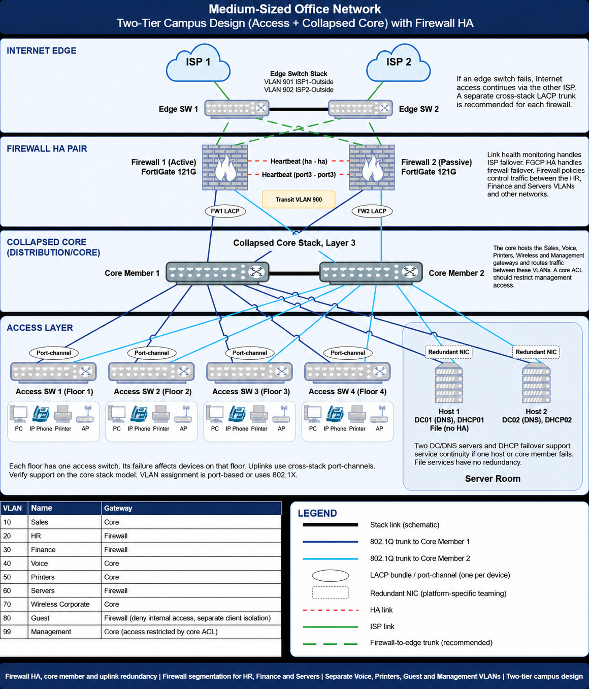
This article explains how the devices are connected and the logic that the installation follows. Device-specific configuration steps and commands are out of scope.
Dual ISP Design at the Internet Edge Layer
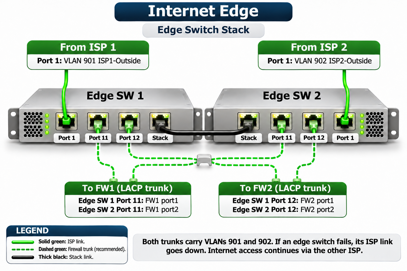
The 2 ISP connections terminate on the edge switch stack, which consists of Edge SW 1 and Edge SW 2. ISP 1 connects to Edge SW 1 on VLAN 901, and ISP 2 connects to Edge SW 2 on VLAN 902. Keeping each ISP in a separate outside VLAN means that the IP blocks, gateways and NAT rules can be managed without being confused with each other.
A separate cross-stack LACP trunk is planned between the edge stack and each FortiGate. The 2 ports of each firewall connect one to Edge SW 1 and the other to Edge SW 2. These trunks carry both ISP VLANs, so whichever firewall is active can reach both ISPs.
The stack is what allows cables that go to 2 different switches to be combined in a single port-channel. In LACP, each switch identifies itself with a system ID, and the other side bundles only the links on which it sees the same system ID. The stack turns 2 physical switches into a single logical switch that runs with a single control plane, so the FortiGate sees the same system ID on both links and places both in a single port-channel.
Without the stack, the 2 switches would respond with different system IDs. In that case the FortiGate bundles only the links that come from the same peer, and the other link is not included in the port-channel and remains on standby. Although there are 2 cables, redundancy and bandwidth do not work as expected. In environments that do not use a stack, the same result is achieved with MLAG, in which 2 switches present a shared LACP identity over a peer link. The equivalent of this design is vPC on Cisco and VSX on Aruba.
The port mappings are shown in the table below.
|
Switch |
Port |
Connection |
Configuration |
|
Edge SW 1 |
Port 1 |
ISP 1 |
Access, VLAN 901 |
|
Edge SW 2 |
Port 1 |
ISP 2 |
Access, VLAN 902 |
|
Edge SW 1 |
Port 11 |
FW1 port1 |
FW1 LAG member, VLAN 901 and 902 |
|
Edge SW 2 |
Port 11 |
FW1 port2 |
FW1 LAG member, VLAN 901 and 902 |
|
Edge SW 1 |
Port 12 |
FW2 port1 |
FW2 LAG member, VLAN 901 and 902 |
|
Edge SW 2 |
Port 12 |
FW2 port2 |
FW2 LAG member, VLAN 901 and 902 |
The operational tasks at this stage are carried out on the edge stack and on the FortiGate together. On the edge stack, VLAN 901 and VLAN 902 are created, each Port 1 is configured as an access port in the relevant VLAN, and the Port 11 and Port 12 pairs are turned into trunks that carry both VLANs, as a separate link aggregation group (LAG) for each firewall. On the FortiGate, separate VLAN interfaces are defined for VLAN 901 and VLAN 902 on this aggregate interface.
A default route is defined for both ISPs, but the route preferences are set with distance or priority values so that the primary ISP is selected. For the backup exit to work, a valid route towards the second ISP, a firewall policy that allows traffic in that direction and a suitable source NAT must also be in place.
ISP failover is planned with Link Health Monitor. The FortiGate sends regular probe packets to the defined targets through the primary ISP and withdraws the related static route when it considers the primary path to have failed. From that point, traffic continues over the route of the backup ISP. Unless Remote Link Failover is also enabled on the HA side, this ISP failover does not cause an FGCP role change, and the active member stays the same. When the ISP changes, the NAT rule also changes, so the public source IP address changes. For this reason, existing sessions must not be expected to survive, and open connections are re-established on the client side.
In terms of failure behaviour, when Edge SW 1 goes out of service, the ISP 1 connection attached to it also goes out of service. The LAG members of the firewalls that go to Edge SW 2 stay in the forwarding state, and if the LAGs are configured so that they can run with a single member, Internet access continues through ISP 2. The aim of redundancy at this stage is the continuity of Internet access, not the survival of a single ISP.
Support for a cross-stack port-channel depends on the switch model and the stack technology. The trunk between the firewall and the edge is the recommended design, and this support must be verified before implementation.
Firewall HA Pair with FortiGate 121G
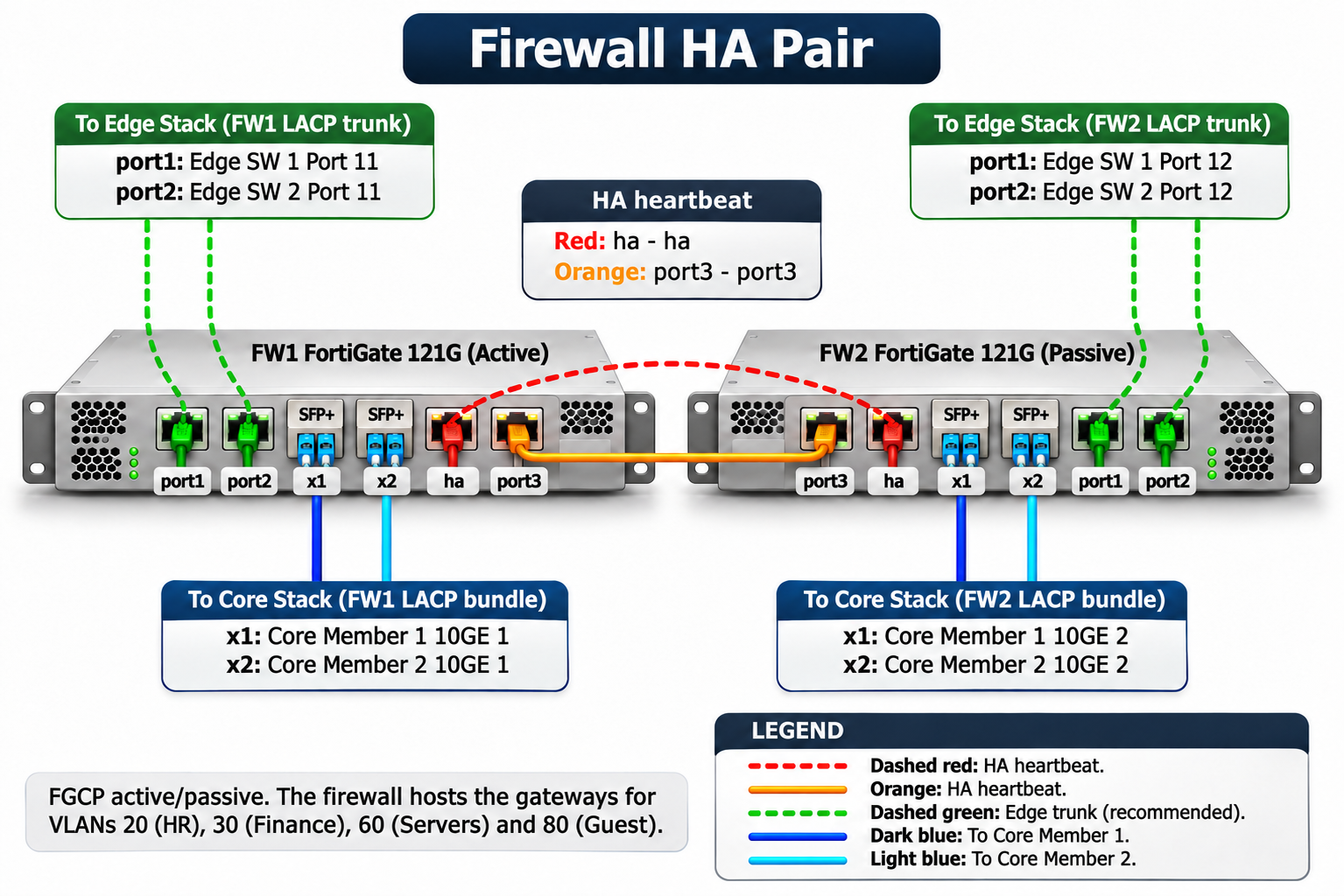
At the firewall layer, 2 FortiGate 121G units run in active/passive mode with FGCP (FortiGate Clustering Protocol). FW1 processes traffic as the active member, while FW2 remains on standby and keeps the configuration and state information synchronised. The difference between the 121G and the 120G is the internal SSD, so logs can be kept on the device and historical traffic analysis can be done without a separate log server.
There are 2 independent heartbeat paths between the 2 firewalls. The first is established between the dedicated ha ports, and the second between the port3 ports. While both paths are working, if one is lost the members continue to communicate over the other. If all heartbeat communication is lost while both members are running, a split-brain condition can occur, in which both members consider themselves active. The second independent path reduces this risk.
The edge-side connection of the firewalls is made through port1 and port2, and the core-side connection through x1 and x2, which are 10GE SFP+ ports. Each firewall connects to the core with its own LACP bundle, which is distributed across the 2 core members. When one of the core members goes out of service, the core connection of the firewall continues as long as the remaining link is in the forwarding state and the minimum active link condition allows a single member.
|
Port |
FW1 Connection |
FW2 Connection |
Purpose |
|
port1 |
Edge SW 1 Port 11 |
Edge SW 1 Port 12 |
Edge LACP trunk |
|
port2 |
Edge SW 2 Port 11 |
Edge SW 2 Port 12 |
Edge LACP trunk |
|
x1 |
Core Member 1 10GE 1 |
Core Member 1 10GE 2 |
Core LACP bundle |
|
x2 |
Core Member 2 10GE 1 |
Core Member 2 10GE 2 |
Core LACP bundle |
|
ha |
FW2 ha |
FW1 ha |
Heartbeat 1 |
|
port3 |
FW2 port3 |
FW1 port3 |
Heartbeat 2 |
On the operational side, the 2 devices are first aligned to the same model and the same FortiOS version. Then the group name, password, mode and heartbeat interfaces are defined in the HA settings. The aggregate interfaces towards the edge and the core, the VLAN interfaces and the transit VLAN 900 interface are configured on the active member and synchronised to the cluster. The gateway of the HR, Finance, Servers and Guest VLANs is on this firewall, so the interfaces of these VLANs are also defined as VLAN interfaces on the aggregate towards the core.
When the active member fails, FW2 takes the active role. FGCP uses virtual MAC addresses on the cluster interfaces, so the gateway MAC address does not change on the neighbouring devices. For existing sessions to continue after a failover, the Session Pickup setting must be enabled.
A separate LAG is created on the edge and on the core for each physical FortiGate. If the passive member takes part in LACP negotiation, the switch must support separate LAGs for the same cluster MAC address. If this support is not available, the participation of the secondary member in negotiation is disabled in the way that suits the FortiOS version in use. In this case, the time that the new active member needs to establish LACP during a failover can lengthen the switchover.
Routing and Transit VLAN at the Collapsed Core Layer
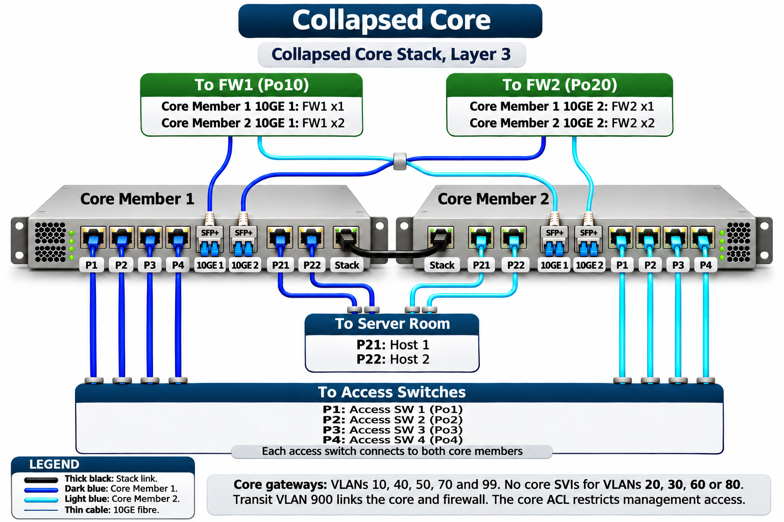
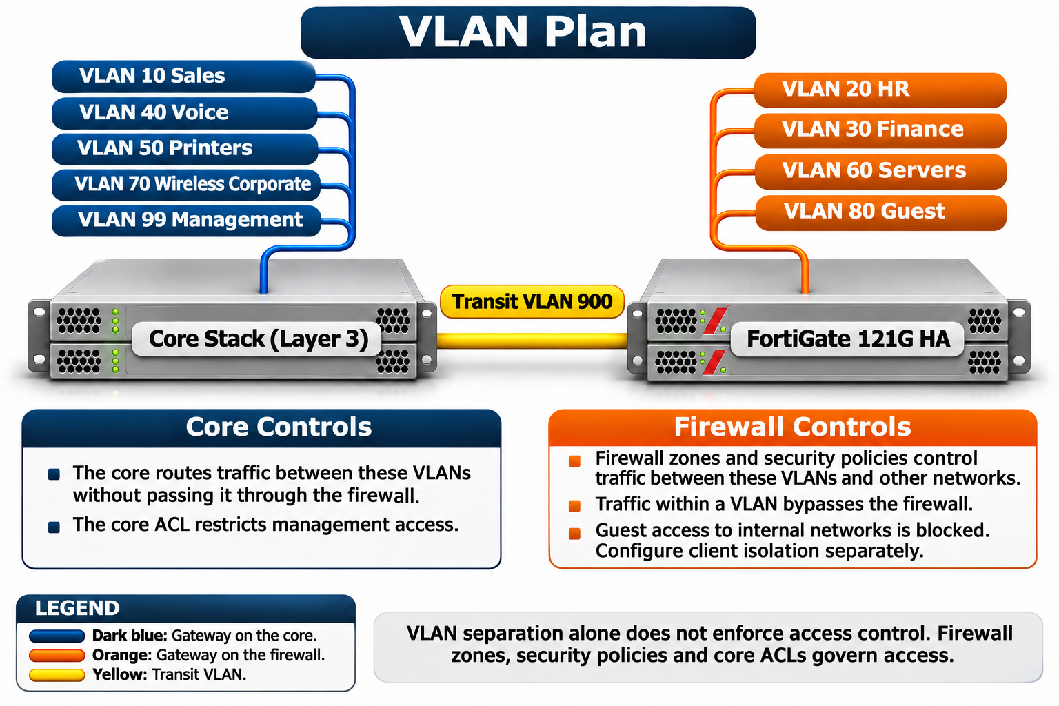
The core layer is a Layer 3 switch stack of 2 members. Core Member 1 and Core Member 2 are managed as a single logical switch, which makes it possible to connect a device with a single port-channel distributed across the 2 members. As the gateway of the Sales, Voice, Printers, Wireless Corporate and Management VLANs, the core hosts an SVI for these VLANs.
The HR, Finance, Servers and Guest VLANs are carried on the core at Layer 2 only and reach the FortiGate over the bundles that go to the firewall. If an active SVI with an IP address is created in these subnets while IP routing is enabled on the core, a connected route appears on the core, and traffic from the core can bypass the firewall. The outbound path of the clients that use the FortiGate as their gateway does not change, so the forward and return traffic can take different paths and asymmetric routing can occur. For this reason, there must be no SVI on the core for these VLANs.
|
Port |
Core Member 1 |
Core Member 2 |
Port-channel |
|
10GE 1 |
FW1 x1 |
FW1 x2 |
Po10 |
|
10GE 2 |
FW2 x1 |
FW2 x2 |
Po20 |
|
P1 - P4 |
Access SW 1 - 4, Uplink 1 |
Access SW 1 - 4, Uplink 2 |
Po1 - Po4 |
|
P21 |
Host 1 NIC 1 |
Host 1 NIC 2 |
Depends on the teaming method |
|
P22 |
Host 2 NIC 1 |
Host 2 NIC 2 |
Depends on the teaming method |
Layer 3 communication between the core and the firewall is established over transit VLAN 900. This VLAN is carried on the existing LACP bundles that go to the firewalls, so it does not need a separate physical connection. The routing logic is summarised in the table below.
|
Device |
Destination |
Next Hop |
|
Core stack |
0.0.0.0/0 (Internet and the VLANs with a firewall gateway) |
Transit VLAN 900 IP address of the FortiGate |
|
FortiGate |
Subnets of VLAN 10, 40, 50, 70 and 99 |
Transit VLAN 900 IP address of the core |
|
FortiGate |
0.0.0.0/0 |
Gateway of the active ISP |
In this design the forward and return traffic take the same path, so the stateful inspection of the FortiGate does not drop sessions because of asymmetric routing. Traffic between the VLANs on the core is routed on the core without passing through the firewall. For this reason, access to the Management VLAN from the other core VLANs must be restricted with ACLs defined on the core.
When a core member goes out of service, the firewalls, access switches and hosts continue to work over their connections to the other member. For this, the remaining member of each bundle must be in the forwarding state and the minimum active link condition at both ends must allow a single member. The stack does not completely remove the risks that come from the shared software, the control plane and the stack connection. This is why it is important to carry out stack software updates in a planned maintenance window.
Access Layer and Cross-Stack Port-Channel
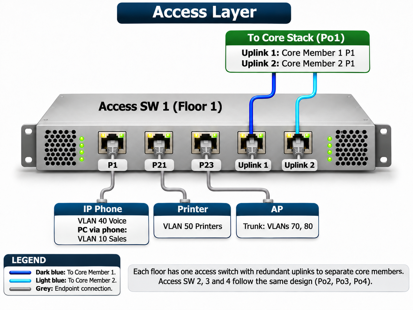
Each floor has 1 access switch, and these switches operate at Layer 2. There is no gateway for the user VLANs on the access switches. Only an IP address in the Management VLAN is defined for management purposes. The 2 uplinks of each access switch, one to Core Member 1 and the other to Core Member 2, form a single cross-stack port-channel on the core stack.
When one of the uplinks is lost or a core member goes out of service, the connection of the floor continues if the remaining member is in the forwarding state and the minimum active link condition at both ends allows a single member. The 2 uplinks work as a single logical connection, so there is also no link blocked by Spanning Tree. The access switch itself is a single device, and if it fails, all devices on that floor are affected.
|
Port |
Connection |
VLAN |
Mode |
|
Uplink 1 |
Core Member 1 P1 |
User VLANs and Management |
Po1 member, trunk |
|
Uplink 2 |
Core Member 2 P1 |
User VLANs and Management |
Po1 member, trunk |
|
P1 |
IP phone and the PC behind it |
Voice 40, Data 10 |
Access and voice VLAN |
|
P21 |
Printer |
50 |
Access |
|
P23 |
AP |
70 and 80 |
Trunk |
The Voice VLAN for the IP phones and the Sales VLAN for the PC behind the phone are defined on the same port. LLDP-MED or CDP can be used so that the phone learns the Voice VLAN automatically. The AP port is configured as a trunk that carries the Wireless Corporate and Guest VLANs.
The departments are spread across the floors, so VLAN assignment is not tied to the floor. Static assignment per port is possible, and dynamic VLAN assignment based on user or device identity with 802.1X can also be used. With dynamic assignment, a RADIUS server such as NPS returns the Tunnel-Type, Tunnel-Medium-Type and Tunnel-Pvt-Group-ID attributes to the switch as the result of authentication, and these attributes determine the VLAN of the port.
The other floors are built in the same way. Access SW 2, 3 and 4 connect to ports P2, P3 and P4 on the core respectively and form port-channels Po2, Po3 and Po4.
Domain Controller, DNS and DHCP Continuity in the Server Room
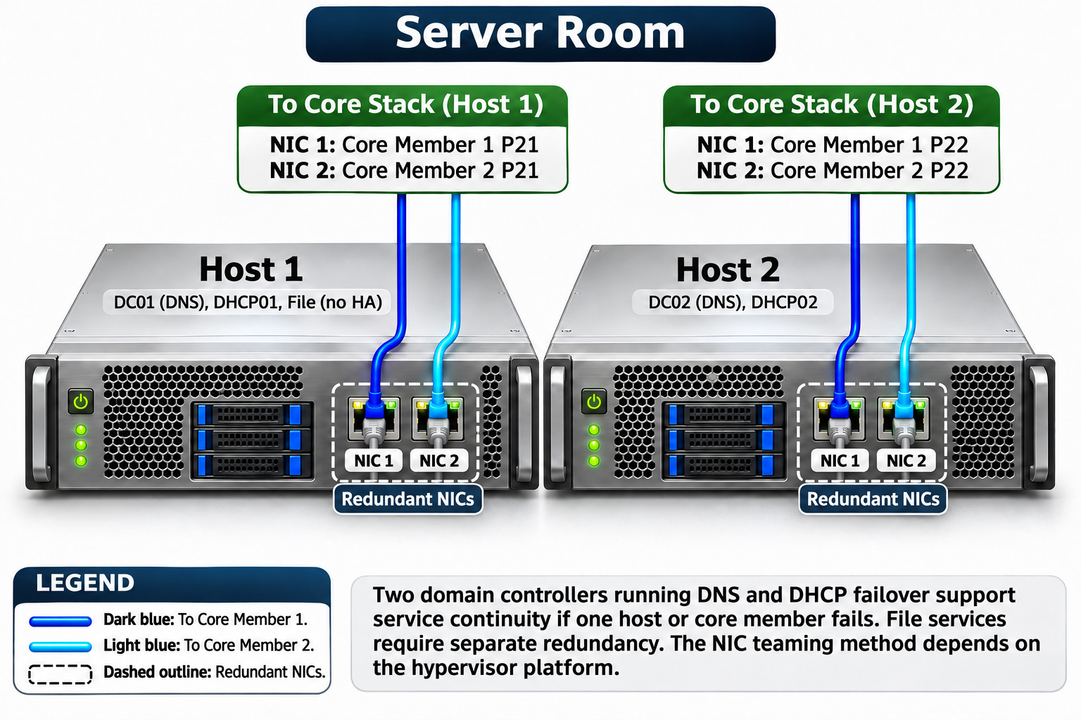
There are 2 hypervisor hosts in the server room. DC01, DHCP01 and the file server run on Host 1, and DC02 and DHCP02 run on Host 2. The 2 NICs of each host connect one to Core Member 1 and the other to Core Member 2. As a result, the host does not lose its network connection when a single NIC of the host or a core member goes out of service.
|
Host |
NIC |
Core Port |
Services |
|
Host 1 |
NIC 1 |
Core Member 1 P21 |
DC01 (DNS), DHCP01, File |
|
Host 1 |
NIC 2 |
Core Member 2 P21 |
DC01 (DNS), DHCP01, File |
|
Host 2 |
NIC 1 |
Core Member 1 P22 |
DC02 (DNS), DHCP02 |
|
Host 2 |
NIC 2 |
Core Member 2 P22 |
DC02 (DNS), DHCP02 |
The teaming method to use for the host connections depends on the hypervisor platform. Switch Embedded Teaming (SET), the recommended method on Hyper-V, works in switch-independent mode and does not support LACP. In this case, no port-channel is created for the host ports on the core. On VMware ESXi, LACP is supported only on a vSphere Distributed Switch and cannot be used with a standard vSwitch.
On the domain controller side, 2 separate matters must be assessed independently of each other. Running the 2 DCs on different hosts provides continuity of the Active Directory service. For DNS continuity, the clients must use the addresses of both reachable AD DNS servers. These addresses can be distributed with DHCP or defined statically. If only 1 DNS server is defined on the client and this server does not respond, new DNS queries that are not in the cache fail.
DHCP Failover is configured per scope on Windows Server, and service continuity applies only to the scopes added to the failover relationship. In client VLANs that use the central DHCP service and are in a different subnet from the servers, DHCP relay must be defined so that it delivers requests to both failover partners. In VLANs whose gateway is on the core, the relay is configured on the core, and in VLANs whose gateway is on the firewall, it is configured on the FortiGate interface. The Servers VLAN, which is in the same subnet as the servers, does not need a relay, and no relay is added to the transit and ISP outside VLANs. For Guest, the configuration follows the DHCP service that is selected.
This design supports service continuity against the failure of a single host or core member. However, no separate redundancy mechanism is defined for the file service on Host 1. If continuity of this service is required, a separate solution such as DFS Namespaces and DFS Replication must be planned.
VLAN Plan and Gateway Placement
The VLAN plan determines where the gateway of each VLAN is and at which point traffic is inspected. The table below summarises this distribution.
|
VLAN |
Name |
Gateway |
Access Control |
|
10 |
Sales |
Core |
Core ACL |
|
20 |
HR |
Firewall |
FortiGate security policy |
|
30 |
Finance |
Firewall |
FortiGate security policy |
|
40 |
Voice |
Core |
Core ACL |
|
50 |
Printers |
Core |
Core ACL |
|
60 |
Servers |
Firewall |
FortiGate security policy |
|
70 |
Wireless Corporate |
Core |
Core ACL |
|
80 |
Guest |
Firewall |
FortiGate security policy, deny to internal networks |
|
99 |
Management |
Core |
Restricted access with core ACL |
VLAN separation alone does not provide access control. Devices in the same VLAN communicate directly over Layer 2, and this traffic does not pass through the firewall. The actual control is applied in the zone and security policy design on the FortiGate for the VLANs with a firewall gateway, and in the core ACLs for the VLANs with a core gateway.
If more than 1 VLAN is placed in the same zone on the FortiGate, the behaviour of traffic inside the zone is determined by the intrazone setting. According to the FortiOS 7.4.7 CLI Reference, the default value of this setting is deny. If communication is required between HR and Finance in the same zone, this permission must be defined with an explicit policy, and if an existing zone is used, the effective intrazone value and the policies must also be checked.
For the Guest VLAN, access to the internal networks is blocked with firewall policies. The source of the DHCP and DNS services for guest clients must be planned separately. Isolation of guest clients from each other is not provided by the Internet access rule. This isolation must be configured separately on the wireless network side.
The most important lesson from this design is that the scope of redundancy must be defined clearly. This design provides firewall HA, core member and uplink redundancy. The access switches and the file service remain as points that need separate measures. Stating this clearly in the design document means that expectations are managed correctly during a failure.
This article covered a 2-tier Campus Network design based on the Collapsed Core model for a medium-sized office, stage by stage from the Internet edge to the server room. The design treats the access layer and the combined distribution/core layer, the FortiGate HA pair in front of it and the edge switch stack that terminates 2 ISPs as a single whole.
At the Internet edge, keeping the 2 ISPs in separate outside VLANs and using a separate cross-stack LACP trunk for each physical firewall makes access to both ISPs possible, whichever firewall is active. The active/passive design built with FortiGate FGCP supports redundancy at the firewall layer with 2 independent heartbeat paths and LACP bundles distributed across the 2 core members.
At the Collapsed Core layer, the gateway placement, the symmetric routing established over the transit VLAN and the firewall-gateway VLANs that have no SVI on the core determine the point at which segmentation is enforced. At the access layer, uplink redundancy is supported with a cross-stack port-channel, and in the server room, service continuity is supported with 2 domain controllers, 2 AD DNS servers and DHCP Failover.
The VLAN plan makes clear whether access control is applied with core ACLs or with FortiGate zones and security policies, depending on whether the gateway is on the core or on the firewall. The single access switch and the file service without redundancy are the points that are outside the redundancy scope of this design and must be planned separately.
I hope you find it useful...
Feel free to share your thoughts and questions about this article in the comments below. Every contribution helps the content reach more people and makes for a more useful discussion.