IPv6 is the network layer protocol that the IETF designed to replace IPv4, and it uses a 128-bit address space. Its task of identifying a device on the network is the same as in IPv4, but the length of the address, its notation, the address types and the way an address is assigned to a device were all redesigned. For this reason, treating IPv6 as a longer version of IPv4 means missing most of the subject.
The 32-bit address space of IPv4 provides about 4.3 billion addresses. The number of devices connected to the Internet exceeded this figure a long time ago, and the free IPv4 pool of IANA was exhausted in 2011. Solutions such as NAT, private address blocks and CGNAT extended the life of IPv4, but they also added a layer that breaks end-to-end connectivity, makes management harder and complicates troubleshooting. The IPv6 addressing structure solves this shortage by enlarging the address space, and NAT is no longer a mandatory component.
The larger address space also brought fundamental changes to the addressing logic. Addresses are written in hexadecimal instead of decimal, a prefix length is used instead of a subnet mask, the broadcast concept is removed completely, and an interface can have more than 1 IPv6 address at the same time. A solid understanding of the network ID, host ID and subnet mask logic in IPv4 makes these differences much easier to interpret. For this foundation, you can read my article titled IPv4 Addressing, IP Classes and Subnetting Logic.
The following sections cover the bit structure of an IPv6 address, the compression rules, prefix notation, the parts of a global unicast address and the subnetting logic in IPv6. They then examine the unicast, multicast and anycast address types, how the interface ID is generated, the address assignment methods and how these addresses appear in Windows.
Structure of an IPv6 Address
To interpret an IPv6 address correctly, you first need to see how the address is built. In IPv4, the 32-bit address is divided into 4 octets and each octet is written in decimal. In IPv6, the 128-bit address is divided into 8 hextets and each hextet is written in hexadecimal. Because the bit length is 4 times greater, the notation, the compression rules and the way the network and interface parts are shown have changed accordingly.
The structure of the address is read in 3 layers. The first layer is how the 128 bits are divided into hextets and how many bits each character represents. The second layer is how long addresses are compressed according to the RFC 5952 standard and how a compressed address is expanded again. The third layer is the prefix length value, which replaces the subnet mask and shows which bits of the address identify the network and which bits identify the interface. Once these 3 layers are clear, the address types and the subnetting logic in the later sections are much easier to follow.
128-Bit Address Space and Hextet Structure
An IPv6 address consists of 128 bits. This means 2128, that is, 340,282,366,920,938,463,463,374,607,431,768,211,456 addresses. Because writing such a long value in binary or decimal is not practical, IPv6 addresses are written in the hexadecimal number system.
The 128 bits are divided into 8 groups of 16 bits each, and the groups are separated by colons. In technical literature, each group is called a hextet. Because a hexadecimal character represents 4 bits, each hextet consists of 4 characters. The hextet is the IPv6 equivalent of the IPv4 octet.
The table below lists the binary and decimal equivalents of the hexadecimal characters. This table is used as a direct reference when you work at bit level in IPv6 addresses, for example when you determine where a prefix ends.
|
Hex |
Binary |
Decimal |
Hex |
Binary |
Decimal |
|
0 |
0000 |
0 |
8 |
1000 |
8 |
|
1 |
0001 |
1 |
9 |
1001 |
9 |
|
2 |
0010 |
2 |
a |
1010 |
10 |
|
3 |
0011 |
3 |
b |
1011 |
11 |
|
4 |
0100 |
4 |
c |
1100 |
12 |
|
5 |
0101 |
5 |
d |
1101 |
13 |
|
6 |
0110 |
6 |
e |
1110 |
14 |
|
7 |
0111 |
7 |
f |
1111 |
15 |
The diagram below shows how an example IPv6 address is divided into 8 hextets, together with the binary equivalent of the first hextet. I will use the same address throughout the article, so that you can follow which part of the address each section refers to.
 2001 : 0db8 : abcd : 0010 : 0215 : 5dff : fe0a : 1b2c
 ---- : ---- : ---- : ---- : ---- : ---- : ---- : ----
  H1     H2     H3     H4     H5     H6     H7     H8
 16bit  16bit  16bit  16bit  16bit  16bit  16bit  16bit

 8 Hextet x 16 bit = 128 bit

 H1 = 2001  ->  0010 0000 0000 0001
                 2    0    0    1
IPv6 Address Compression Rules
In its full form, an IPv6 address consists of 32 hexadecimal characters and 7 separators. Because most addresses contain consecutive zeros, RFC 4291 defines 2 compression rules, and RFC 5952 sets the standard representation so that these rules are applied in a single, consistent way. This standard prevents different people from writing the same address in different ways.
The table below summarises what the compression rules state and how they are applied.
|
Rule |
Description |
Example |
|
Omitting leading zeros |
The leading zeros of each hextet are not written. If the whole hextet is zero, a single 0 is kept. |
0db8 → db8
0010 → 10
0000 → 0 |
|
:: for consecutive zero groups |
Consecutive hextets that are all zero are represented once by ::. |
2001:db8:0:0:0:0:0:1 → 2001:db8::1 |
|
:: is used only once |
If :: is used twice in an address, it is not possible to determine how many zero groups are on which side, and the address is invalid. |
2001:db8::1::1 is invalid |
|
The longest run of zeros is compressed |
If there is more than 1 run of zeros, :: is applied to the longest run. If the runs are of equal length, the first run is compressed. |
2001:db8:0:0:1:0:0:1 → 2001:db8::1:0:0:1 |
|
:: is not used for a single zero hextet |
According to RFC 5952, :: must represent at least 2 consecutive zero hextets. |
2001:db8:0:1:1:1:1:1 stays as it is |
|
Use of lower case |
Hexadecimal characters are written in lower case. Upper case is accepted as valid, but the standard representation is lower case. |
2001:DB8::1 → 2001:db8::1 |
To see how the rules work together, it helps to place the full and compressed representations of several addresses next to each other.
|
Full Representation |
Standard Compressed Representation |
|
2001:0db8:0000:0000:0000:ff00:0042:8329 |
2001:db8::ff00:42:8329 |
|
2001:0db8:abcd:0010:0215:5dff:fe0a:1b2c |
2001:db8:abcd:10:215:5dff:fe0a:1b2c |
|
2001:0db8:0000:0001:0000:0000:0000:0001 |
2001:db8:0:1::1 |
|
fe80:0000:0000:0000:0215:5dff:fe0a:1b2c |
fe80::215:5dff:fe0a:1b2c |
|
0000:0000:0000:0000:0000:0000:0000:0001 |
::1 |
|
0000:0000:0000:0000:0000:0000:0000:0000 |
:: |
To expand a compressed address to its full form, count the visible hextets and subtract the result from 8. For example, the address 2001:db8::ff00:42:8329 shows 5 hextets, so the :: sign represents 3 0000 hextets. This expansion is often needed when you write a firewall rule, analyse logs or compare 2 addresses.
2 IPv6 addresses that are written differently can be the same address. When you compare logs and rules, converting the addresses to the RFC 5952 standard representation first prevents incorrect matches.
Prefix Length and Prefix Notation
IPv6 does not use a subnet mask. Which bits of the address identify the network and which bits identify the interface is shown by the prefix length added to the end of the address, in a similar way to CIDR notation in IPv4. The expression 2001:db8:abcd:10::/64 shows that the first 64 bits are the prefix and that the remaining 64 bits are reserved for the interface ID.
When a prefix is written, the bits outside the prefix are treated as zero. An address assigned to an interface is written together with its prefix length. The notation 2001:db8:abcd:10::25/64 states that this address belongs to the 2001:db8:abcd:10::/64 prefix.
The table below shows the prefix lengths that are most common in the field and their typical uses.
|
Prefix Length |
Typical Use |
Number of /64 Subnets Contained |
|
/32 |
Typical block assigned to an ISP or LIR by a Regional Internet Registry |
4,294,967,296 |
|
/48 |
Block assigned to an enterprise location or site |
65,536 |
|
/56 |
Block assigned to a small office or home user |
256 |
|
/64 |
A single subnet, that is, a VLAN or network segment |
1 |
|
/127 |
Point-to-point link between 2 routers |
- |
|
/128 |
A single address, loopback or host route |
- |
The standard prefix length for end-user and server subnets is /64. Because the Stateless Address Autoconfiguration (SLAAC) mechanism is built on a 64-bit interface ID, SLAAC does not work in a subnet smaller than /64. For point-to-point links between routers, RFC 6164 defines the use of /127.
Parts of a Global Unicast Address
Global unicast addresses are allocated from the 2000::/3 block, which IANA uses for globally unique addressing on the Internet. They are the equivalent of the public IP address in IPv4, but their internal structure is much more orderly. A typical global unicast address is divided into 3 parts on the basis of a /48 site prefix and /64 subnets.
|<---------- 48 bit ---------->|<- 16 bit ->|<--------------- 64 bit --------------->|
+------------------------------+------------+-----------------------------------------+
|    Global Routing Prefix     | Subnet ID  |              Interface ID               |
+------------------------------+------------+-----------------------------------------+
       2001 : 0db8 : abcd      :    0010    :     0215 : 5dff : fe0a : 1b2c

|<------------------ Prefix /64 ------------------>|
The table below lists the role of each part and its value in the example address.
|
Part |
Length |
Example Value |
Role |
|
Global Routing Prefix |
48 bits |
2001:db8:abcd |
The part that the ISP or Regional Internet Registry assigns to the organisation and that is routed on the Internet |
|
Subnet ID |
16 bits |
0010 |
The part that the organisation uses internally to separate its subnets from each other |
|
Interface ID |
64 bits |
0215:5dff:fe0a:1b2c |
The part that identifies the interface within the subnet, the equivalent of the host ID in IPv4 |
This division is not mandatory. It is the most common design model. If the ISP assigns a /56 to the organisation, the subnet ID is reduced to 8 bits and the organisation is limited to 256 subnets. The interface ID stays at 64 bits in almost every scenario because of the /64 standard.
Subnetting Logic in IPv6
In IPv6, subnetting is done by including bits from the subnet ID field in the prefix. The logic is the same as in IPv4, and each borrowed bit doubles the number of subnets. The difference is that the calculation is based on the number of subnets, not on the number of hosts. Because each /64 subnet holds 264, that is, 18,446,744,073,709,551,616 addresses, the number of hosts is no longer a design constraint in practice.
When you do subnetting in IPv6, it is preferable to align the prefix boundaries with multiples of 4 bits. This is called the nibble boundary. Because boundaries such as /48, /52, /56, /60 and /64 match the boundary of a single hexadecimal character, the prefixes can be read easily from the address itself and the documentation becomes simpler.
Let us repeat the 16 networks example from my IPv4 Subnetting article in IPv6. We have the 2001:db8:abcd::/48 block and we want to divide it into 16 equal parts. Because 24 = 16, 4 bits are added to the prefix and the new prefix length is /52. The 4 added bits correspond to the first hexadecimal character of the subnet ID. For this reason, the networks advance in steps of 1000 hex on the first character of the 4th hextet.
|
Network |
Prefix |
Subnet ID Range |
Number of /64 Subnets Contained |
|
1 |
2001:db8:abcd::/52 |
0000 - 0fff |
4,096 |
|
2 |
2001:db8:abcd:1000::/52 |
1000 - 1fff |
4,096 |
|
3 |
2001:db8:abcd:2000::/52 |
2000 - 2fff |
4,096 |
|
4 |
2001:db8:abcd:3000::/52 |
3000 - 3fff |
4,096 |
|
5 |
2001:db8:abcd:4000::/52 |
4000 - 4fff |
4,096 |
|
6 |
2001:db8:abcd:5000::/52 |
5000 - 5fff |
4,096 |
|
7 |
2001:db8:abcd:6000::/52 |
6000 - 6fff |
4,096 |
|
8 |
2001:db8:abcd:7000::/52 |
7000 - 7fff |
4,096 |
|
9 |
2001:db8:abcd:8000::/52 |
8000 - 8fff |
4,096 |
|
10 |
2001:db8:abcd:9000::/52 |
9000 - 9fff |
4,096 |
|
11 |
2001:db8:abcd:a000::/52 |
a000 - afff |
4,096 |
|
12 |
2001:db8:abcd:b000::/52 |
b000 - bfff |
4,096 |
|
13 |
2001:db8:abcd:c000::/52 |
c000 - cfff |
4,096 |
|
14 |
2001:db8:abcd:d000::/52 |
d000 - dfff |
4,096 |
|
15 |
2001:db8:abcd:e000::/52 |
e000 - efff |
4,096 |
|
16 |
2001:db8:abcd:f000::/52 |
f000 - ffff |
4,096 |
In each /52 block, 52 bits are allocated to the prefix, so 12 bits remain for the subnet ID. This means 212 = 4,096 /64 subnets.
Assume that the 2001:db8:abcd:1000::/52 block is assigned to a location. Each VLAN at this location receives the next /64 prefix from this block.
|
VLAN |
Subnet ID |
Prefix |
|
1st VLAN |
1000 |
2001:db8:abcd:1000::/64 |
|
2nd VLAN |
1001 |
2001:db8:abcd:1001::/64 |
|
3rd VLAN |
1002 |
2001:db8:abcd:1002::/64 |
|
... |
... |
... |
|
4,096th VLAN |
1fff |
2001:db8:abcd:1fff::/64 |
In IPv4, the number of usable hosts is calculated with the formula 2h-2. The 2 subtracted addresses are the network ID and the broadcast address. This calculation does not exist in IPv6.
Because there is no broadcast address, the last address of the subnet is not reserved in the IPv4 sense. Instead, certain interface ID values are reserved for anycast use. The table below lists these values, which must not be assigned to hosts in a /64 subnet.
|
Interface ID |
Use |
Defining RFC |
|
0000:0000:0000:0000 |
Subnet-Router Anycast |
RFC 4291 |
|
fdff:ffff:ffff:ff80 - fdff:ffff:ffff:ffff |
Reserved Subnet Anycast, 128 values in total |
RFC 2526 |
The Subnet-Router Anycast address, whose interface ID is all zeros, is used by the routers connected to that subnet. The reserved interface ID values are collected in an IANA registry by RFC 5453, and a generated interface ID must stay outside these values.
Point-to-point links that use a /127 prefix are subject to separate rules under RFC 6164. The Subnet-Router Anycast address is not used on these links, so both addresses in the /127 can be assigned to router interfaces.
IPv6 Address Types
IPv6 defines 3 address types in RFC 4291. The broadcast address type of IPv4 does not exist in IPv6. The need to reach all devices in a subnet is met by the ff02::1 All-Nodes multicast address. This design removes the broadcast traffic that every device has to process in IPv4, because devices process only the packets of the multicast groups that they have joined.
|
Address Type |
Delivery Model |
Prefix |
Description |
|
Unicast |
One-to-one |
Depends on the type |
Identifies a single interface. The packet is delivered only to that interface. |
|
Multicast |
One-to-many |
ff00::/8 |
Identifies a group of interfaces. The packet is delivered to all interfaces that have joined the group. |
|
Anycast |
One-to-nearest |
From the unicast address space |
Assigned to more than 1 interface. The packet is delivered to the interface that is nearest in routing terms. |
Unicast Addresses
Unicast addresses are divided further according to their scope and purpose. The type of an IPv6 address can be identified from its prefix. The table below summarises the unicast address types, their prefixes and their routing behaviour.
|
Unicast Type |
Prefix |
Scope |
Routed on the Internet |
IPv4 Equivalent |
|
Global Unicast |
2000::/3 |
Global |
Yes, except special-purpose blocks |
Public IP |
|
Link-Local |
fe80::/10 |
A single link |
No, it does not pass through a router |
169.254.0.0/16 APIPA |
|
Unique Local |
fc00::/7 |
Within the organisation |
No |
RFC 1918 private IP |
|
Loopback |
::1/128 |
The device itself |
No |
127.0.0.1 |
|
Unspecified |
::/128 |
No address |
No |
0.0.0.0 |
Global Unicast Addresses
IANA currently allocates global unicast addresses from the 2000::/3 block. Because the first 3 bits of this block are 001, global unicast addresses start with 2 or 3 in practice. IANA assigns sub-blocks from this block to the Regional Internet Registries, and they assign sub-blocks to ISPs and organisations.
Not every address in the 2000::/3 block is routed on the Internet. Some blocks in the IANA Special-Purpose registry, such as the 2001:db8::/32 documentation block, are inside this space but are not routed globally.
Global unicast addresses are unique on the Internet and provide end-to-end communication without NAT. This does not mean that a device on the internal network is directly reachable from the Internet. Access is determined by the firewall policy. Because the hiding effect that NAT provides as a side effect in IPv4 does not exist in IPv6, inbound traffic rules must be defined deliberately.
Link-Local Addresses
Every interface with IPv6 enabled receives a link-local address automatically, even if there is no other configuration. This address comes from the fe80::/10 block, but in practice the first 64 bits are used as fe80:0000:0000:0000 and the address appears as fe80::/64. Link-local addresses are valid only between devices on the same link, and a router does not forward them to another network.
The APIPA address in IPv4 is a fallback mechanism that takes effect when DHCP fails. The link-local address in IPv6 always exists and is required for the protocol to work. Router discovery runs over the Neighbor Discovery Protocol (NDP) with link-local addresses. Because the source address of a Router Advertisement message must be a link-local address, the address that clients see as the default gateway is also the link-local address of the router in most cases.
This rule has 1 exception. When the device does not have a valid address yet, for example in the Neighbor Solicitation message that it sends during Duplicate Address Detection, the unspecified address :: is used as the source address.
When more than 1 interface is active on a device, each interface has its own link-local address. Because all of these addresses use the same fe80::/64 prefix, the address itself does not show which interface a packet to a link-local address will leave from. This information is given by the zone ID, which is added to the end of the address with the % sign.
|
Operating System |
Zone ID Format |
Example Notation |
|
Windows |
Interface index number |
fe80::f64d:5cff:fe47:c080%11 |
|
Linux |
Interface name |
fe80::f64d:5cff:fe47:c080%eth0 |
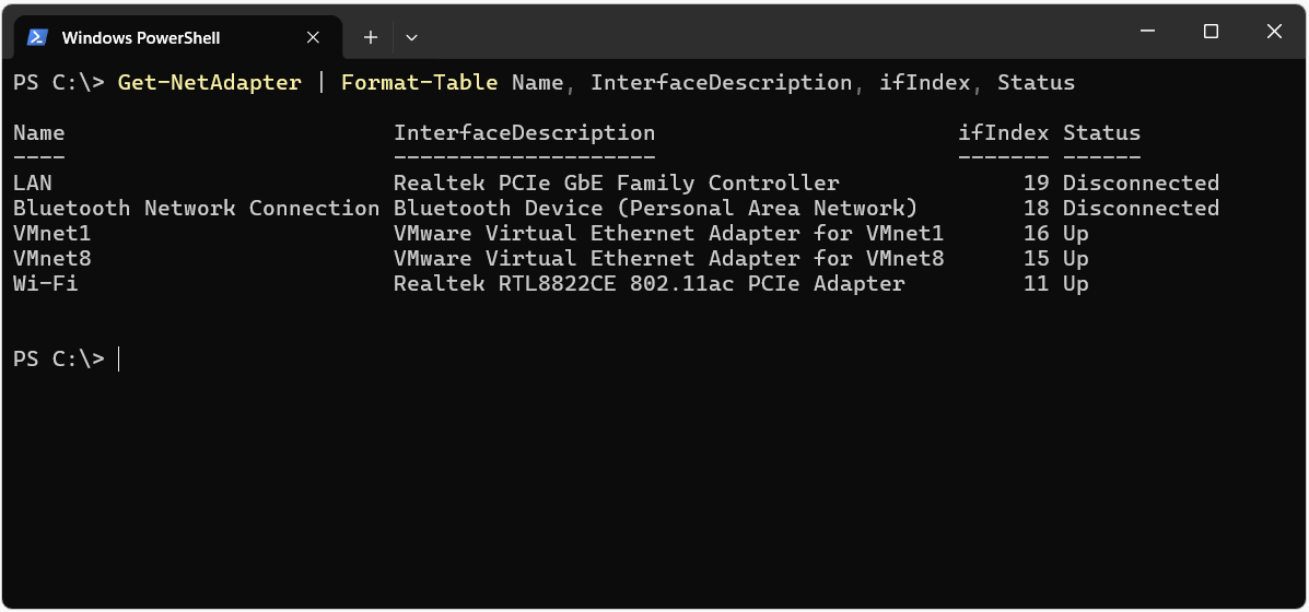
The interface index value that Windows uses as the zone ID is shown in the ifIndex column of the Get-NetAdapter output.
Get-NetAdapter | Format-Table Name, InterfaceDescription, ifIndex, Status
In the output below, the ifIndex value of the Wi-Fi interface, which has the active connection, is 11. Every link-local address reached through this interface is used together with the %11 zone ID.
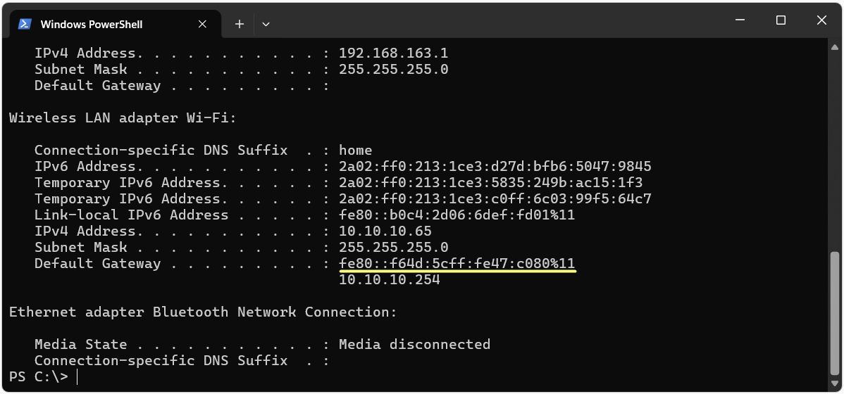
The same information is also visible in the ipconfig output. Windows shows link-local addresses together with the zone ID in this output.
The output below shows the link-local address of the Wi-Fi interface itself together with the link-local address of the router, which appears as the default gateway. The %11 value at the end of both addresses is the same as the ifIndex number in the Get-NetAdapter output.
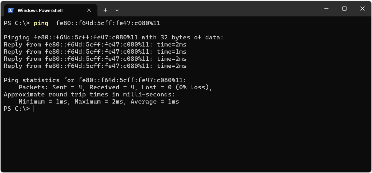
The address on the Default Gateway line can be used in the ping command exactly as it is, together with its zone ID.
 ping  fe80::f64d:5cff:fe47:c080%11
       |                        |
       |                        +-- Zone ID, ifIndex value of the Wi-Fi interface
       +--------------------------- Link-local address of the router, Default Gateway value
When the correct zone ID is given, the packet is sent through the Wi-Fi interface and the router replies.
Unique Local Addresses
Unique Local Addresses (ULA) are defined in RFC 4193. They are used inside an organisation and are not routed to the Internet. The prefix is defined as fc00::/7. The 8th bit of this block is the L flag, and the fd00::/8 block, where the L flag is 1, is used for locally generated addresses. Because no assignment mechanism is defined for the fc00::/8 block, where the L flag is 0, ULA addresses in the field start with fd.
|<- 8 bit ->|<------ 40 bit ------>|<- 16 bit ->|<------- 64 bit ------->|
+-----------+----------------------+------------+------------------------+
|    fd     |      Global ID       | Subnet ID  |      Interface ID      |
+-----------+----------------------+------------+------------------------+
     fd       12 : 3456 : 789a     :    0001    :  Interface ID

 Site Prefix  = fd12:3456:789a::/48
 Subnet       = fd12:3456:789a:1::/64
The point that separates ULA from RFC 1918 addresses is the 40-bit Global ID field. This field must be generated randomly. In IPv4, when 2 organisations merge and both of them use 10.0.0.0/8 or 192.168.1.0/24, readdressing is unavoidable. In ULA, because the Global ID is generated randomly, the probability that 2 organisations use the same prefix is very low, and the networks can be merged without a conflict. Prefixes that are easy to remember but not random, such as fd00::/48, remove this advantage.
ULA addresses can be used on the same interface together with global unicast addresses. In this case, Windows decides which source and destination address to select according to the prefix policy table.
Loopback and Unspecified Addresses
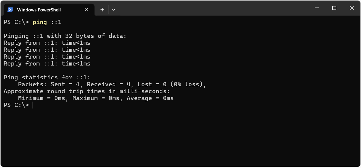
The loopback address is ::1/128 and it has the same role as 127.0.0.1 in IPv4. A packet sent to this address does not leave the device and returns to the IPv6 stack of the device itself. In IPv4, the whole 127.0.0.0/8 block is reserved for loopback, but IPv6 defines a single address for loopback.
When you ping the loopback address, the IPv6 stack of the device answers the packet before it reaches any interface. For this reason, the response time appears as less than 1 ms, and the test confirms that the IPv6 stack works, independently of the network connection.
The unspecified address is ::/128 and it indicates that an interface does not have an address yet. It is not assigned to an interface and it is not used as a destination address. During Duplicate Address Detection, the device does not have a valid address yet, so :: is used as the source address in the messages that it sends. If a service listens on ::, this means that it listens on all IPv6 addresses, in the same way as 0.0.0.0 in IPv4.
Special-Purpose Address Blocks
In addition to the types above, there are blocks that are reserved for specific purposes or that have been deprecated over time. When you see these prefixes in logs, routing tables or transition technologies, knowing what they represent makes troubleshooting faster.
|
Prefix |
Name |
Status |
Purpose |
|
2001:db8::/32 |
Documentation |
Active |
Reserved for documentation and examples. It is not used on real networks. |
|
::ffff:0:0/96 |
IPv4-Mapped |
Active |
Used by a dual-stack application to represent its IPv4 connections over an IPv6 socket. An example notation is ::ffff:192.168.1.10. |
|
64:ff9b::/96 |
NAT64 Well-Known Prefix |
Active |
Used in NAT64 and DNS64 scenarios to represent IPv4 addresses inside an IPv6 address. |
|
2002::/16 |
6to4 |
Not recommended |
A transition technology used to tunnel IPv6 traffic over IPv4. |
|
2001::/32 |
Teredo |
Not recommended |
A transition technology that provides IPv6 tunnelling over UDP for devices behind NAT. |
|
fec0::/10 |
Site-Local |
Deprecated |
Deprecated by RFC 3879 and replaced by unique local addresses. |
|
::/96 |
IPv4-Compatible |
Deprecated |
Defined for old transition mechanisms and deprecated by RFC 4291. |
Multicast Addresses
Multicast addresses come from the ff00::/8 block, so every address that starts with ff is a multicast address. The role of multicast in IPv6 is much wider than in IPv4. Address resolution, router discovery and reaching all devices, which IPv4 does with broadcast, are done with multicast in IPv6. Which multicast groups an interface joins is managed by the Multicast Listener Discovery (MLD) protocol. MLD is the IPv6 equivalent of IGMP in IPv4.
The first 16 bits of a multicast address define the type of the address and the area in which it is valid.
|<- 8 bit ->|<- 4 bit ->|<- 4 bit ->|<------------- 112 bit ------------->|
+-----------+-----------+-----------+-------------------------------------+
| 1111 1111 |   Flags   |   Scope   |              Group ID               |
+-----------+-----------+-----------+-------------------------------------+
     ff           0           2       :: 1

 ff02::1  ->  Flags = 0 (Well-Known), Scope = 2 (Link-Local), Group ID = 1
If the T bit in the Flags field is 0, the address is a permanent well-known address assigned by IANA. If it is 1, the address represents a temporarily created multicast group. The Scope field determines how far the packet can be forwarded. Routers check this field to decide whether a multicast packet may cross their boundaries.
|
Scope Value |
Scope |
Description |
|
1 |
Interface-Local |
The packet does not leave the interface. It is used for loopback purposes. |
|
2 |
Link-Local |
The packet stays on the same link and does not pass through a router. |
|
4 |
Admin-Local |
The smallest administrative scope, defined by the administrator. |
|
5 |
Site-Local |
The packet stays within the boundary of a single site. |
|
8 |
Organization-Local |
The packet stays within the boundary that covers multiple sites of the organisation. |
|
e |
Global |
The packet can be routed across the Internet. |
The table below lists the well-known multicast addresses that are most common in the field and their roles. Recognising these addresses in packet captures or in the multicast group lists on a router helps you to identify quickly which protocol the traffic belongs to.
|
Multicast Address |
Group |
Use |
|
ff02::1 |
All-Nodes |
All IPv6 devices on the link. This is the address that replaces broadcast. |
|
ff02::2 |
All-Routers |
All routers on the link. Router Solicitation messages are sent to this address. |
|
ff02::5 |
OSPFv3 Routers |
All OSPFv3 routers |
|
ff02::6 |
OSPFv3 DR |
OSPFv3 designated routers |
|
ff02::9 |
RIPng Routers |
Routers that run RIPng |
|
ff02::fb |
mDNS |
Multicast DNS |
|
ff02::1:2 |
All DHCP Agents |
DHCPv6 servers and relay agents on the link. Clients send their DHCPv6 requests to this address. |
|
ff02::1:3 |
LLMNR |
Link-Local Multicast Name Resolution |
|
ff05::1:3 |
All DHCP Servers |
All DHCPv6 servers within the site |
|
ff02::1:ff00:0/104 |
Solicited-Node |
Address resolution with Neighbor Discovery and Duplicate Address Detection |
Solicited-Node Multicast Address
In IPv4, a device sends an ARP request as a broadcast to learn the MAC address of an IP address in the same subnet. All devices in the subnet have to receive and process this packet. In IPv6, the Neighbor Discovery Protocol performs this task, and the Neighbor Solicitation message is sent only to the solicited-node multicast address of the target address instead of a broadcast.
The solicited-node address is formed by adding the last 24 bits of the unicast address to the end of the ff02::1:ff00:0/104 prefix. The device automatically joins the relevant solicited-node group for every unicast and anycast address on the interface.
 Unicast Address   : 2001:db8:abcd:10:215:5dff:fe0a:1b2c
 Last 24 bits      :                             0a:1b2c

 Fixed Prefix /104 : ff02:0000:0000:0000:0000:0001:ff
 Solicited-Node    : ff02:0000:0000:0000:0000:0001:ff0a:1b2c
 Compressed        : ff02::1:ff0a:1b2c
Because very few addresses in a subnet share the same last 24 bits, the Neighbor Solicitation packet is processed only by the target device in practice. If the switches support MLD snooping, these packets are forwarded only to the ports that have joined the relevant group. When a device receives a new address, it runs Duplicate Address Detection with the same mechanism before it starts to use the address, and it checks whether another device on the network uses this address.
The multicast groups that an interface has joined can be listed in Windows with netsh.
netsh interface ipv6 show joins 11
The output starts with well-known groups such as ff02::1 All-Nodes. The part that needs attention is the solicited-node groups that start with ff02::1:ff further down the list.
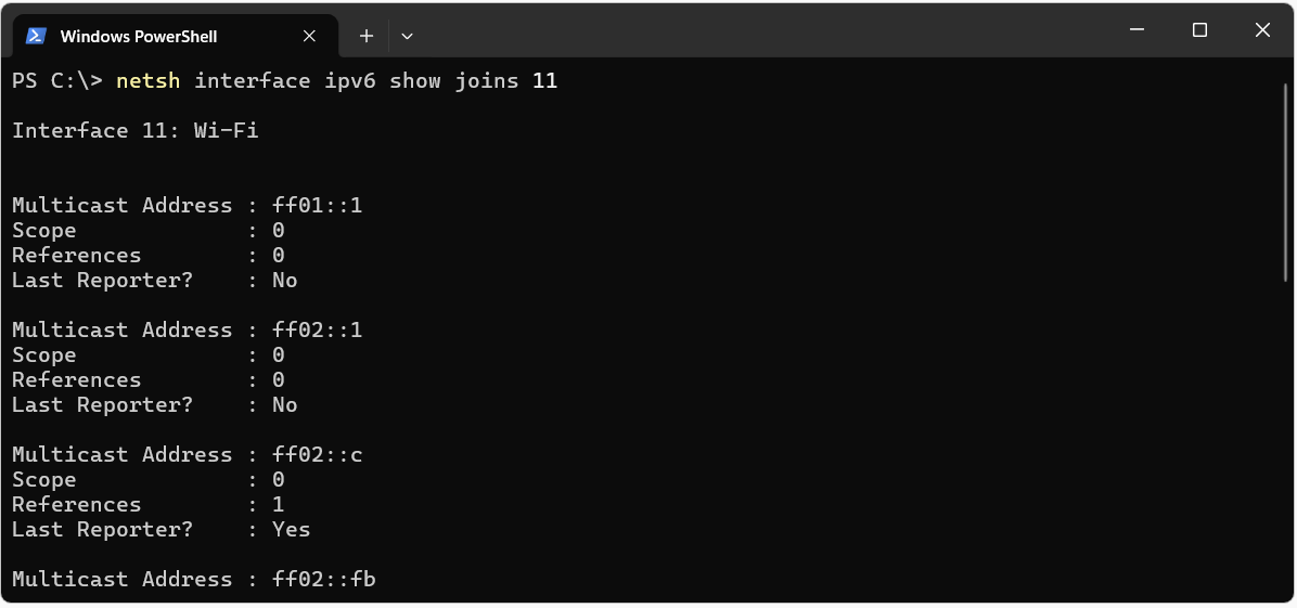
Because the Wi-Fi interface of the computer has 4 IPv6 addresses, a separate solicited-node group has been created for each address.
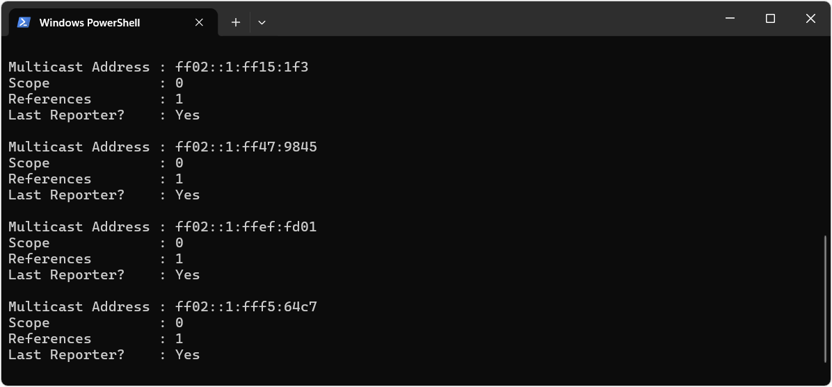
The last part of each group consists of the last 6 hexadecimal characters of the related IPv6 address. Because each hexadecimal character is 4 bits, these 6 characters correspond to the last 24 bits of the address. For example, the last 6 characters of the link-local address fe80::b0c4:2d06:6def:fd01 are ef:fd01. When the fixed ff02::1:ff prefix is added in front of this value, the resulting address ff02::1:ffef:fd01 is the solicited-node multicast address of the link-local address.
|
Address Type |
End of the IPv6 Address |
Last 24 Bits |
Solicited-Node Group |
|
Link-Local |
...6def:fd01 |
ef:fd01 |
ff02::1:ffef:fd01 |
|
Stable Global Unicast |
...5047:9845 |
47:9845 |
ff02::1:ff47:9845 |
|
Temporary |
...ac15:1f3 |
15:01f3 |
ff02::1:ff15:1f3 |
|
Temporary |
...99f5:64c7 |
f5:64c7 |
ff02::1:fff5:64c7 |
Anycast Addresses
An anycast address is a unicast address that is assigned to more than 1 interface at the same time. A packet sent to this address is delivered to the nearest interface according to the metric of the routing protocol. There is no separate address block for anycast. The addresses are taken from the unicast address space and cannot be distinguished from a unicast address by their notation. An address behaves as anycast when it is configured at more than 1 point and included in routing.
RFC 4291 defines a Subnet-Router Anycast address for each subnet. This address is the combination of the subnet prefix and an interface ID that is all zeros. For the 2001:db8:abcd:10::/64 subnet, this address is 2001:db8:abcd:10:: and all routers connected to that subnet listen on it. DNS root servers and large CDN infrastructures also use the anycast logic by advertising the same address from different points around the world.
Interface ID Generation Methods
The interface ID, which is the last 64 bits of an IPv6 address, can be entered manually as a static value, assigned by DHCPv6 or generated automatically by the device. The method used for automatic generation directly determines whether the address stays the same over time and whether the device can be tracked on different networks.
|
Method |
Source |
Behaviour |
Privacy Impact |
|
Modified EUI-64 |
MAC address of the interface |
The same interface ID is generated on every network. |
The MAC address can be read from the address, and the device can be tracked on different networks. |
|
Random interface ID |
Randomly generated value |
It is independent of the MAC address. |
The MAC address is not exposed. |
|
Stable Privacy |
Value generated from the prefix and a secret key |
It stays the same on the same network and changes on a different network. |
It makes address correlation between networks and tracking of the device more difficult. |
|
Temporary Address |
Value that is regenerated periodically |
It is renewed after a certain period. |
It does not leave a permanent identity on outgoing connections. |
Modified EUI-64
The Modified EUI-64 method generates a 64-bit interface ID from the 48-bit MAC address. The MAC address is split in the middle, fffe is inserted between the 2 halves, and the 7th bit of the first byte, that is, the Universal/Local bit, is inverted. The steps are as follows for a MAC address with the 00-15-5D OUI, which is used in Microsoft Hyper-V virtual machines.
|
Step |
Operation |
Result |
|
1 |
The MAC address is taken |
00-15-5D-0A-1B-2C |
|
2 |
The MAC address is split into 2 parts of 24 bits each |
00155D | 0A1B2C |
|
3 |
fffe is inserted between the 2 parts |
00155D FFFE 0A1B2C |
|
4 |
The first byte is converted to binary |
00 = 0000 0000 |
|
5 |
The 7th bit is inverted |
0000 0010 = 02 |
|
6 |
The interface ID is formed |
0215:5dff:fe0a:1b2c |
|
7 |
It is combined with the /64 prefix |
2001:db8:abcd:10:215:5dff:fe0a:1b2c |
If ff:fe appears in the middle of the interface ID, the address was most probably generated with Modified EUI-64 and the MAC address can be calculated back from it. Some network operating systems, such as Cisco IOS, generate link-local addresses with this method by default.
Random Interface IDs and Temporary Addresses
The fact that the MAC address can be read from the address allows the device to be tracked across different networks. For this reason, Windows uses a randomly generated interface ID instead of Modified EUI-64 by default. This behaviour is controlled by the RandomizeIdentifiers value in the Get-NetIPv6Protocol output.
Temporary addresses are defined in RFC 8981 and are renewed at certain intervals. For the prefix that it receives in a Router Advertisement, the device generates a temporary address in addition to its stable address. The temporary address is preferred as the source address for privacy on connections that the client starts. A host that works as a server can use a stable address that is associated with its DNS name to accept incoming connections.
In Windows Client and Windows Server versions, the use of temporary addresses is determined by the UseTemporaryAddresses value. The current state of the system can be verified from the Get-NetIPv6Protocol output.
Get-NetIPv6Protocol | Format-List RandomizeIdentifiers, UseTemporaryAddresses
The output shows 2 settings. If both settings are Enabled, Windows generates IPv6 addresses in a way that protects privacy.
|
Setting |
When Enabled |
When Disabled |
|
RandomizeIdentifiers |
The interface ID is generated randomly. The MAC address is not included in the IPv6 address. |
The interface ID is generated from the MAC address with Modified EUI-64. |
|
UseTemporaryAddresses |
In addition to the stable address, temporary addresses that are renewed at certain intervals are also generated. |
Only the stable address is used. |
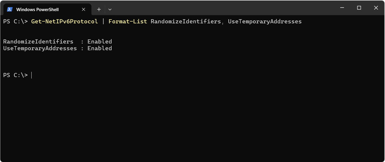
The effect of the RandomizeIdentifiers setting is clear when the 2 real addresses used throughout this article are compared. The first is the link-local address of the Wi-Fi interface of the Windows computer, and the second is the link-local address of the router on the same network. Whether an interface ID was generated from the MAC address can be identified by whether ff:fe appears in the middle of it.
|
Device |
Link-Local Address |
ff:fe in the Middle |
Generation Method of the Interface ID |
|
Windows computer |
fe80::b0c4:2d06:6def:fd01 |
No |
It was generated randomly, and the MAC address cannot be read from the address. |
|
Router |
fe80::f64d:5cff:fe47:c080 |
Yes |
It was generated from the MAC address of the router with Modified EUI-64. |
Because of the RandomizeIdentifiers setting, Windows does not place the MAC address inside the IPv6 address, and this makes it more difficult to track the device on different networks. The router uses Modified EUI-64, so its MAC address is directly inside the address.
IPv6 Address Assignment Methods
In IPv4, a client receives its address either statically or through DHCP. In IPv6, the address assignment process starts with the Router Advertisement (RA) message that the router sends. Through the flags in the RA message, the router tells the client where to obtain its address and where to learn additional information such as DNS. The A flag in the Prefix Information Option indicates the use of SLAAC, the M flag in the RA header indicates the use of stateful DHCPv6, and the O flag indicates the use of DHCPv6 for additional information.
|
Method |
RA Flags |
Address Source |
DNS Information |
Default Gateway |
|
Manual |
- |
Administrator |
Administrator |
Administrator or RA |
|
SLAAC |
A=1, M=0, O=0 |
The client generates it from the prefix in the RA |
RDNSS option in the RA |
RA |
|
SLAAC and Stateless DHCPv6 |
A=1, M=0, O=1 |
The client generates it from the prefix in the RA |
DHCPv6 |
RA |
|
Stateful DHCPv6 |
M=1, usually A=0 |
DHCPv6 server |
DHCPv6 |
RA |
The last column of the table shows the point that most often confuses administrators who come with IPv4 habits. DHCPv6 does not give the client default gateway information. In a dynamic IPv6 configuration, the default router is learned from the Router Advertisement and usually appears as the link-local address of the router. The default route can also be configured statically by the administrator. If RA messages are blocked on the network or the router does not send RAs, and no static default route is defined, the client cannot leave its subnet even if DHCPv6 assigns addresses.
The router must also send RAs on a network where addresses are assigned with stateful DHCPv6. DHCPv6 does not carry default gateway information. In a dynamic configuration, this information comes from the Router Advertisement.
Address Lifecycle
Automatically configured addresses in IPv6 have a lifetime. The Preferred Lifetime and Valid Lifetime values in the Router Advertisement determine when the address moves from one state to another. Windows shows these states in the AddressState field of the Get-NetIPAddress output.
|
State |
Description |
|
Tentative |
The address is in the Duplicate Address Detection process and cannot be used yet. |
|
Preferred |
The address is valid and can be used for new connections. |
|
Deprecated |
The Preferred Lifetime has expired. Existing connections continue, but the address is not used for new connections. |
|
Invalid |
The Valid Lifetime has expired and the address is removed from the interface. |
|
Duplicate |
Duplicate Address Detection found that another device uses the address. |
The Deprecated state becomes important in scenarios where the ISP changes the prefix. The address of the old prefix moves to the Deprecated state, and the address of the new prefix is brought into use without dropping open connections. In this way, readdressing can be done without interruption.
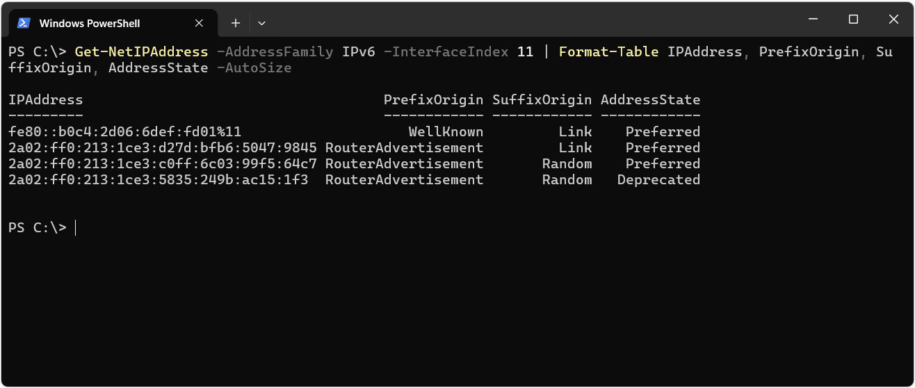
The command below shows the source and the state of the addresses of the Wi-Fi interface together.
Get-NetIPAddress -AddressFamily IPv6 -InterfaceIndex 11 | Format-Table IPAddress, PrefixOrigin, SuffixOrigin, AddressState -AutoSize
The output below lists the link-local address, the stable global unicast address and 2 temporary addresses on the same interface. The AddressState column explains why 2 separate temporary addresses appear in the ipconfig output. The temporary address that ends with ...99f5:64c7 is in the Preferred state and is used for new connections. The previous temporary address, which ends with ...ac15:1f3, is in the Deprecated state. When a new temporary address is generated, the previous address is not removed immediately. It stays on the interface until the Valid Lifetime expires.
Examining IPv6 Addresses in Windows
A Windows interface with IPv6 enabled usually shows more than 1 address instead of a single address. This is not an error. It is a natural result of the IPv6 design. A client can have a link-local address, a stable global unicast address generated from a Router Advertisement and a temporary address at the same time. The table below explains what the fields in the ipconfig /all output mean.
|
ipconfig Field |
Address Type |
Description |
|
IPv6 Address |
Global Unicast or Unique Local |
Stable address obtained through SLAAC, DHCPv6 or static configuration |
|
Temporary IPv6 Address |
Global Unicast |
Address that is preferred as the source address on connections started by the client and that is renewed periodically |
|
Link-local IPv6 Address |
Link-Local |
Address that starts with fe80:: and is shown together with the zone ID |
|
Default Gateway |
Link-Local |
Router address learned from the Router Advertisement, which usually starts with fe80:: |
|
DHCPv6 Client DUID |
- |
Unique identifier with which the device identifies itself to the DHCPv6 server |
In PowerShell, the Get-NetIPAddress cmdlet shows where each address comes from and which state it is in more clearly than ipconfig. The commands below list the addresses, the interface ID generation settings, the multicast groups that the interface has joined and the prefix policy table.
Get-NetIPAddress -AddressFamily IPv6 | Format-Table IPAddress, InterfaceAlias, PrefixLength, PrefixOrigin, SuffixOrigin, AddressState -AutoSize

Get-NetIPv6Protocol | Format-List RandomizeIdentifiers, UseTemporaryAddresses

netsh interface ipv6 show joins

Get-NetPrefixPolicy
The PrefixOrigin field in the Get-NetIPAddress output shows where the prefix part of the address comes from. The SuffixOrigin field is used to distinguish whether the interface ID is permanent or temporary. The Link value does not mean that the permanent interface ID was generated from the MAC address. As the IPV6-ADDR-07 image also shows, when RandomizeIdentifiers is enabled, Windows shows the Link value for randomly generated permanent interface IDs as well.
|
Field |
Value |
Meaning |
|
PrefixOrigin |
WellKnown |
The prefix is defined by the protocol, such as fe80::/64 or ::1 |
|
PrefixOrigin |
RouterAdvertisement |
The prefix was learned from a Router Advertisement |
|
PrefixOrigin |
Dhcp |
The prefix came from the DHCPv6 server |
|
PrefixOrigin |
Manual |
The prefix was configured statically |
|
SuffixOrigin |
Link |
Permanent interface ID. When RandomizeIdentifiers is enabled, Windows shows this value for randomly generated permanent interface IDs as well. |
|
SuffixOrigin |
Random |
Interface ID of a temporary address, renewed periodically |
|
SuffixOrigin |
Dhcp |
The whole address was assigned by DHCPv6 |
|
SuffixOrigin |
Manual |
The interface ID was configured statically |
Windows selects source and destination addresses according to the prefix policy table, which is based on RFC 6724, and it prefers IPv6 to IPv4 by default. When a connection problem is caused by IPv6, the most common mistake is to disable IPv6 on the network adapter. Microsoft does not recommend this approach, because Windows components are tested on the assumption that IPv6 is enabled, and services that use IPv6 over loopback can be affected.
Microsoft does not recommend disabling IPv6 in Windows. If IPv4 must take priority, set the DisabledComponents value under Tcpip6 to 0x20 so that IPv4 is preferred through the prefix policy.
Comparison of IPv4 and IPv6 Addressing
Seeing the IPv4 equivalents of the concepts explained so far in a single table helps to make the transition between the 2 protocols clear. In particular, knowing what IPv4 concepts such as broadcast, ARP and APIPA become in IPv6 helps you to check the right place during troubleshooting.
|
Feature |
IPv4 |
IPv6 |
|
Address length |
32 bits |
128 bits |
|
Notation |
Decimal, 4 octets separated by dots |
Hexadecimal, 8 hextets separated by colons |
|
Network definition |
Subnet mask or CIDR |
Prefix length |
|
Standard subnet size |
Depends on the requirement |
/64 |
|
Addresses not assigned to hosts |
Network ID and broadcast |
Subnet-Router Anycast and the Reserved Subnet Anycast range |
|
Reaching all devices |
Broadcast |
ff02::1 All-Nodes multicast |
|
Address resolution |
ARP broadcast |
NDP and solicited-node multicast |
|
Multicast group management |
IGMP |
MLD |
|
Automatic local address |
169.254.0.0/16 APIPA, only when DHCP fails |
fe80::/10 link-local, always on every interface |
|
Internal address |
RFC 1918 private IP |
fd00::/8 unique local |
|
Loopback |
127.0.0.1 |
::1 |
|
Unspecified |
0.0.0.0 |
:: |
|
Automatic address assignment |
DHCP |
SLAAC, stateless DHCPv6, stateful DHCPv6 |
|
Default gateway source |
DHCP or static |
Router Advertisement or static |
|
Addresses per interface |
Usually 1 |
Usually more than 1 |
|
Need for NAT |
Common because of address shortage |
Not required for addressing |
You do not need to memorise much to read IPv6 addressing comfortably. If you can read the type of an address from its prefix and the subnet it belongs to from its prefix length, you can interpret most of the addresses that you see in routing tables, firewall rules and packet captures. How the interface ID was generated cannot always be identified from the address itself. A value generated with Modified EUI-64 can be recognised by the ff:fe in the middle of it. In Windows, the setting that actually shows the interface ID generation behaviour is the RandomizeIdentifiers value in the Get-NetIPv6Protocol output. When you move on to address planning, dividing the /48 or /56 block on the nibble boundary and allocating a /64 to each VLAN is a sound starting point that does not require readdressing later as the environment grows.
This article covered, on a technical basis, how the IPv6 addressing structure is built, starting from the 128-bit address space and continuing through the hextet structure, the compression rules and prefix notation. It explained how IPv6 answers the address shortage of IPv4 and why this solution changed the addressing logic fundamentally.
It examined the global routing prefix, subnet ID and interface ID parts of the global unicast address, address planning based on /48 and /64, and the IPv6 subnetting logic with the nibble boundary approach. It showed, in comparison with the subnetting calculations in IPv4, that subnetting in IPv6 is planned by the number of subnets and not by the number of hosts.
It covered in detail the unicast, multicast and anycast address types, the scope of link-local and unique local addresses, the multicast structure that works according to the Scope field and the solicited-node mechanism that replaces broadcast. It also evaluated how the interface ID is formed with Modified EUI-64, random generation and temporary addresses, together with their privacy impact.
Finally, it examined the relationship of the SLAAC, stateless DHCPv6 and stateful DHCPv6 methods with the Router Advertisement flags, the source of the default gateway information, the address lifecycle and the verification of IPv6 addresses in Windows. This information is a sound reference when you plan IPv6 addresses in dual-stack environments and troubleshoot connection problems caused by IPv6.
I hope you find it useful...
Feel free to share your thoughts and questions about this article in the comments below. Every contribution helps the content reach more people and makes for a more useful discussion.