Fibre optic cables carry data as pulses of light instead of electrical signals. This difference largely removes the basic limits of copper cables, which are electromagnetic interference, signal attenuation and distance restrictions. The channel that carries the light is the core, which is made of very high purity silicon dioxide (SiO₂) glass. Inside the glass, light travels at about 2/3 of its speed in a vacuum, which is about 200,000 km per second.
In this article, I first explain which properties make SiO₂ a suitable medium for fibre, and then the layer structure of a fibre cable from the inside to the outside. After that, I move on to zipcord and multi-fibre cable types, the difference between multimode and singlemode, the OM and OS classes, and the distances that these classes support in the Ethernet standards. In telecommunications, data centres and network infrastructures that require high bandwidth, choosing the right fibre depends on reading these structural differences correctly.
1- Silicon Dioxide (SiO₂) and the Optical Basis of Fibre
Optical Purity and Low Attenuation
Both the core and the cladding of a fibre are made of SiO₂ glass. What separates the two is doping. The core is usually doped with germanium dioxide (GeO₂) to raise its refractive index. The refractive index of the cladding stays slightly lower than that of the core, and total internal reflection, which keeps the light inside the core, comes from this small index difference.
The main reason SiO₂ is chosen for fibre is that it absorbs very little light at certain wavelengths. During manufacturing, metal ions, gas bubbles and especially OH (hydroxyl) residues are reduced to a minimum. As these residues decrease, the scattering and absorption of light also decrease. Today, attenuation in a standard singlemode fibre is about 0.3-0.4 dB/km at 1310 nm and about 0.2 dB/km at 1550 nm. The loss is not zero, but it is far too low to be compared with copper, and this is what makes long-distance transmission possible.
Thermal, Chemical and Mechanical Properties
SiO₂ glass has a high melting point and is largely chemically inert. It keeps its dimensional stability when the temperature changes. Even so, glass is not completely independent of moisture. Water and OH ions increase attenuation (the water peak around 1383 nm is the result of this) and, over time, can cause micro-cracks to grow on the glass surface, which is known as stress corrosion. This is why loose tubes, jelly compound and water-blocking layers are used in outdoor cables.
On the mechanical side, glass is hard, and it behaves in a brittle way because of the flaws on its surface. A fibre can be bent within a certain bend radius because the glass diameter is very small, 125 µm, which keeps the bending stress limited; the glass diameter, not the coating diameter, sets the strength limits in bending. The polymer coating on the glass is not the layer that makes the fibre bendable. Its job is to protect the glass surface against mechanical damage, preserve the strength of the glass and reduce microbending losses. The durability that makes the cable usable in the field comes from protective layers such as the aramid yarn, the central strength member and the outer jacket.
Resistance to Electromagnetic Interference and the Distance Advantage
The signal carried in fibre is light, and glass is a dielectric material. For this reason, the induced noise seen in copper cables near motors, near high-voltage lines or in industrial environments with strong electromagnetic fields does not affect fibre. This resistance does not come from SiO₂ itself. It comes from the fact that transmission uses light in an insulating medium. The metal layers of armoured cables that contain corrugated steel tape or a steel central member are assessed separately for earthing and lightning protection.
The difference is also clear in terms of distance. In the common BASE-T Ethernet standards that run over CAT cables, from 10BASE-T to 10GBASE-T, the maximum channel length is 100 metres; 25GBASE-T and 40GBASE-T are defined only up to 30 metres. In fibre, the distance ranges from a few hundred metres to tens of kilometres, depending on the fibre class and the Ethernet standard in use. Fibre also has a limit, but this limit is defined separately for each standard. I give these values in the tables in the multimode and singlemode sections of the article.
Areas of Use
The areas that use fibre most heavily are telecommunications backbones, data centres and campus networks. Outside these areas, fibre bundles carry images in medical devices such as endoscopes, interference-resistant links are built over fibre in military communication systems, and communication lines that run along the same route as high-voltage lines in the energy sector are built over fibre.
2- Layer Structure of a Fibre Optic Cable
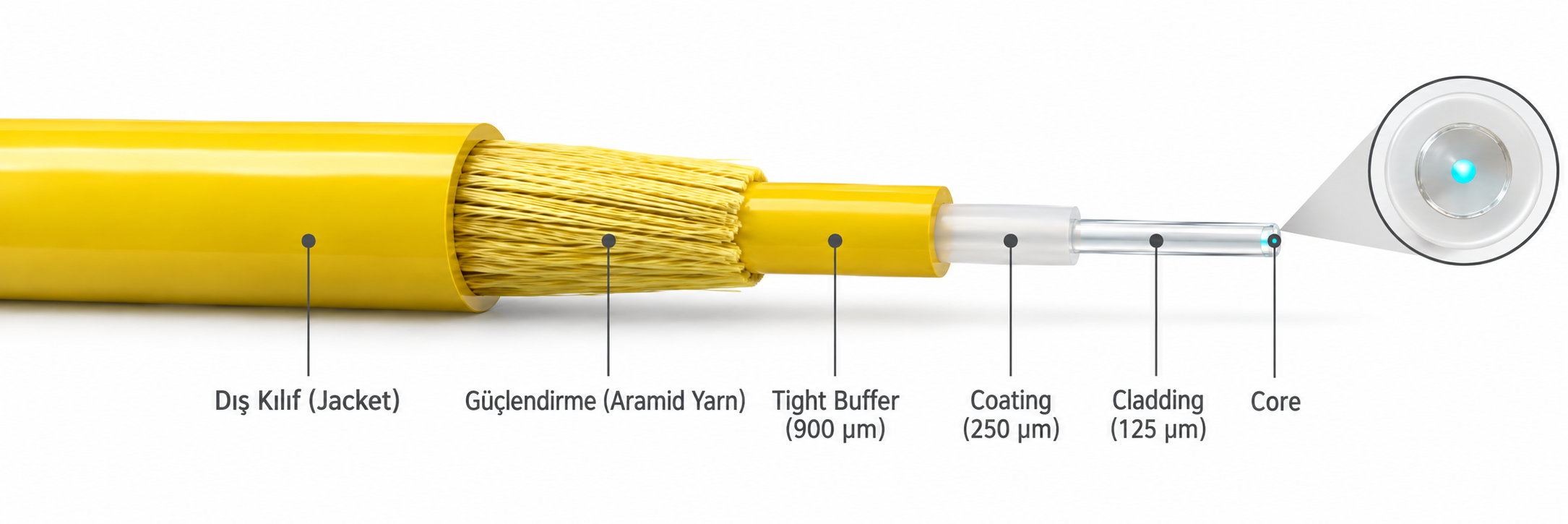
The glass that carries the light inside a fibre cable is only a few microns in diameter. Every other layer exists to protect this glass and to make it safe to use in the field. The diagram below shows the layers of a single-fibre indoor cable from the inside to the outside.
|
Layer |
Material / Structure |
Diameter / Size |
Function |
|
Core |
GeO₂-doped SiO₂ glass |
Singlemode: 8-9 µm
Multimode: 50 / 62.5 µm |
The core in which the light is carried |
|
Cladding |
SiO₂ glass |
125 µm |
Keeps the light inside the core |
|
Coating |
Acrylate coating |
About 250 µm |
Protects the glass fibre mechanically |
|
Tight buffer |
Plastic buffer layer |
900 µm |
Provides additional mechanical protection and allows the fibre to be terminated with a connector |
|
Strength member |
Aramid yarn (Kevlar) |
- |
Carries the tensile force |
|
Outer jacket |
PVC / LSZH |
About 2-3 mm |
Provides the outer protection of the cable |
The values in the table summarise what the layers are, but how a fibre behaves in the field is determined by how these layers work together. The core and the cladding determine how the light is carried, the coating and the tight buffer determine the mechanical strength of the glass, and the aramid yarn and the jacket determine how well the cable withstands pulling and environmental conditions. For this reason, I cover the layers one by one, from the inside to the outside.
✅ Core
The core is the innermost layer, where the light is carried and data transmission takes place. It is made of SiO₂ glass doped with GeO₂, and its refractive index is slightly higher than that of the cladding. Because of this, the light reflects at the boundary between the core and the cladding and travels inside the core.
Core diameter is the most visible physical property that separates multimode and singlemode fibres. In multimode fibres the core diameter is 50 µm or 62.5 µm, and in singlemode fibres it is about 8-9 µm. However, the core diameter alone does not determine whether the fibre operates with a single mode; the refractive index difference between the core and the cladding (numerical aperture) and the wavelength in use also affect the result.
In singlemode fibre, the shortest wavelength at which only a single mode can propagate is called the cut-off wavelength, and this value is measured under 2 different conditions. The fibre cut-off wavelength (λc), which is measured on a short uncabled fibre, can be higher than the cable cut-off wavelength (λcc), which is measured under cabling and bending conditions; for example, a G.652.D fibre specification gives λc in the 1190-1320 nm range, while λcc is 1260 nm. For standard G.652 fibre, the value used as the limit is a cable cut-off wavelength of 1260 nm or below. This is why cabled singlemode fibre operates with a single mode in the 1310 nm and 1550 nm windows.
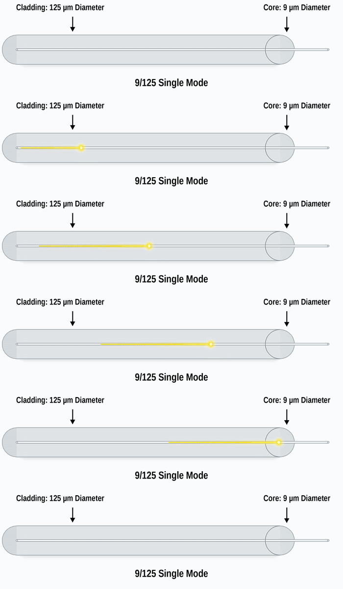
The term 9/125 µm used for singlemode fibre is a nominal size designation. The real values vary by fibre type. For example, the physical core diameter of a standard G.652.D fibre is about 8.2 µm. The mode field diameter (MFD), which describes the area over which the light spreads as it extends from the core into the cladding, is about 9.2 µm at 1310 nm and about 10.4 µm at 1550 nm in the same fibre. For this reason, it is not correct to treat the 9 µm value as exactly equal to either the physical core diameter or the MFD.
✅ Cladding
The cladding is the glass layer that surrounds the core and is drawn together with it as a single piece. Its outer diameter is the same in multimode and singlemode fibres: 125 µm. Its function is optical; with a refractive index slightly lower than that of the core, it makes total internal reflection possible and prevents the light from escaping from the core.
In singlemode fibre, most of the light travels in the core, but part of it extends into the region of the cladding close to the core. This is why the MFD is larger than the physical core diameter. The structure of the cladding does not change according to whether the cable is an indoor or an outdoor type. Protection against the outside environment does not come from the cladding. It comes from the coating, buffer, loose tube, armour and jacket layers that surround it.
✅ Coating
As soon as the glass is drawn, an acrylate coating is applied to it, and the outer diameter of the fibre rises to about 250 µm. The coating usually has 2 layers: the soft inner layer cushions the glass against external mechanical loads, and the hard outer layer protects it against abrasion and environmental effects. In this way, the strength of the glass is preserved and microbending losses are reduced. The structure called bare fibre actually consists of the core, the cladding and the coating.
✅ Tight Buffer
When a tight buffer is added over the coating, the diameter reaches 900 µm. This layer makes the fibre easy to handle and allows it to be terminated directly with a connector. The tight buffer structure is common in indoor cables, but it is not specific to indoor use; there are also indoor/outdoor tight buffer cables manufactured with water-blocking elements and a UV-resistant jacket. The loose tube structure, in which the fibres lie freely inside a tube, is widely used, especially on long outside plant routes.
✅ Strength Member
The strength member takes the tensile force that occurs while the cable is being pulled or while it hangs, so that the glass does not have to. Aramid yarn (Kevlar) is used most often in this layer. Kevlar is light and flexible, and its tensile strength relative to its weight is several times higher than that of steel. This balance is the reason it can carry the tensile load while the cable can still bend.
In outdoor and long-distance cables, in addition to the aramid yarn, a central strength member made of FRP (glass fibre reinforced plastic) or steel is placed at the centre of the cable. This element provides tensile strength and also limits the expansion and contraction of the cable with temperature.
✅ Outer Jacket
The jacket is the outermost layer of the cable and protects the internal structure against moisture, abrasion, chemicals and mechanical impact. Indoor cables usually use PVC (polyvinyl chloride) or LSZH (Low Smoke Zero Halogen). An LSZH jacket is designed to produce low-density smoke during a fire and to prevent the formation of corrosive and acidic gases caused by halogens. When jackets that contain halogens burn, the gases released combine with moisture and form acids that harm human health and damage metal and electronic equipment. This is why LSZH is preferred in server rooms and enclosed spaces.
In outdoor cables, the jacket is usually made of PE (polyethylene), which is resistant to UV light and water. The thickness and material of the jacket affect the cable's resistance to environmental effects and its service life in the field.
3- Fibre Optic Cable Types
The layer structure is the same in every fibre, but how these fibres are brought together inside a cable depends on the intended use. A patch cable that connects 2 devices in a server room and a backbone cable laid between buildings carry the same fibre, but they are very different in terms of cable structure, fibre count and protective layers. In this section, I cover cables according to the number of fibres they carry and their structure: 2-line zipcord cables, multi-fibre cables that gather tens or hundreds of fibres under a single jacket, and multi-core fibre, which contains more than 1 core inside a single fibre. The multimode and singlemode distinction is independent of these types and is explained separately in the later sections.
3.1- Zipcord (Duplex) Fibre Optic Cable
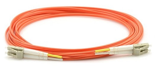
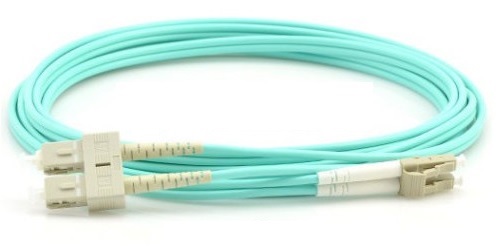
A zipcord fibre optic cable consists of 2 separately jacketed fibre lines joined side by side, and it provides duplex communication. One line is assigned as TX and the other as RX, for sending and receiving data. This gives full-duplex communication along the link. It is manufactured as multimode or singlemode, and its ends are usually terminated with LC-LC or LC-SC connectors.
It is used most in switch-to-switch and transceiver-to-device connections. A fibre that leaves an SFP module installed in a switch and connects directly to a 10G optical port on a server is a typical transceiver-to-device connection. Patch panel-to-switch links inside the server room are also among the places where zipcord is seen most often.
Zipcord cables are also manufactured with an LSZH jacket, and this jacket type makes the cable safe to use in enclosed server rooms. The jacket holds the 2 lines together and makes tidy cabling easier. Lines in different colours or with numbers prevent TX and RX from being confused.
Each line contains an independent optical path with core, cladding, coating and tight buffer layers. Because the glass structure is sensitive to impact, aramid yarn is used inside the lines, and this layer carries the tensile load.
Bending the cable more sharply than the minimum bend radius specified by the manufacturer causes macrobending loss and increases insertion loss. With excessive bending, the glass can break.
Another practical advantage of zipcord is that it allows asymmetric termination. The jackets of the 2 lines can be separated from each other at the end, and each line can be terminated with a different type of connector. For example, if you want to fit an LC connector at one end and an SC connector at the other, you separate the lines at the end of the cable and terminate each one separately. The aim is to match the cable to the port structure of the devices it connects to. This solution is usually preferred in the following cases:
-
Connecting devices of different generations. If an older device has an SC port and the new device has an LC port, one end of the cable is terminated as SC and the other as LC.
-
Compatibility with the existing infrastructure. If the patch panel side has SC ports and the new switches have LC ports, the cable is terminated with 2 different ends instead of replacing the panel.
-
Limited stock. If only an LC-LC cable is available and SC is needed at one end, only that end is re-terminated.
-
Temporary installation and testing. If the devices under test use different port types, a single cable can connect to all of them.
-
Cost and time. Matching the cable to the devices is faster and more economical than standardising all port types.
I mostly see this kind of solution in server rooms and data centres where hardware of different generations works together. Zipcord is one of the few cable types in fibre infrastructure installations that you recognise when you see it and can use without having to think about it.
3.2- Multi-Fibre Cables: 12, 48, 144 and 216 Core
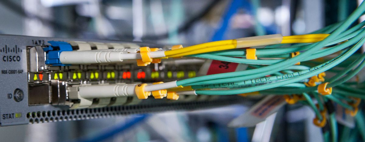
Cables that are called "12 core" or "144 core" in the field consist of a large number of independent fibres gathered under a single outer jacket. Here, the word "core" refers to the number of fibres. Each fibre is a standard single-core fibre with its own core and cladding. These cables are widely used in backbone links between campuses, links between buildings, data centre backbones and carrier infrastructures.
How the fibres are grouped inside the cable depends on the manufacturer's design. The structures in use are central tube, where all fibres lie in a single tube, stranded loose tube, where several tubes are wound around a central member, and ribbon, where the fibres are arranged in flat strips. The number of fibres per tube is not fixed either; for example, a 24-fibre central tube cable can have 24 fibres in a single tube, while in a 216-fibre stranded loose tube cable each of the 18 tubes can carry 12 fibres. In outdoor types, jelly compound or water-blocking elements, aramid yarn and steel armour layers protect the cable against field risks such as moisture, pulling and rodents.
|
Fibre Count |
Typical Use |
|
12 core |
Links between buildings, small campus backbones |
|
48 core |
Campus backbones, industrial facilities, routes that require redundant links |
|
144 core |
Data centre backbones, large campuses, metropolitan carrier lines |
|
216 core |
Carrier backbones and distribution routes that require high fibre density |
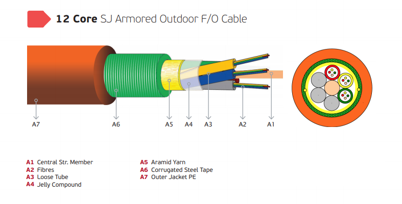
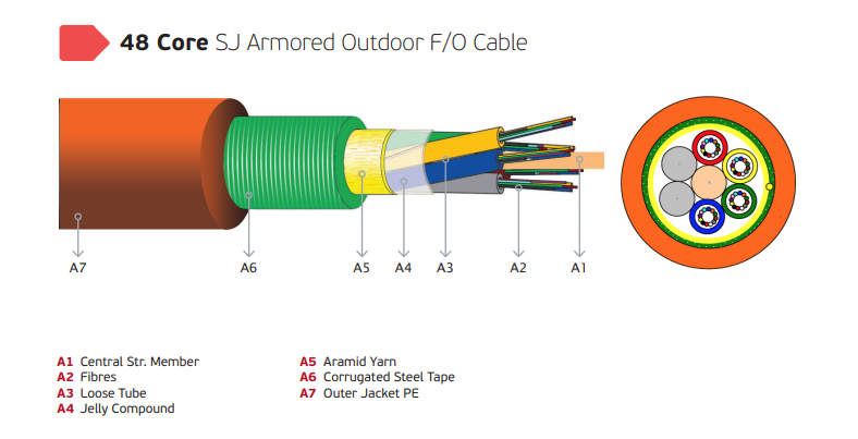
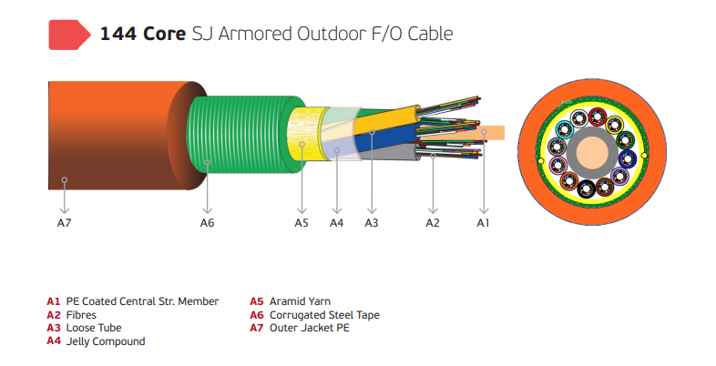
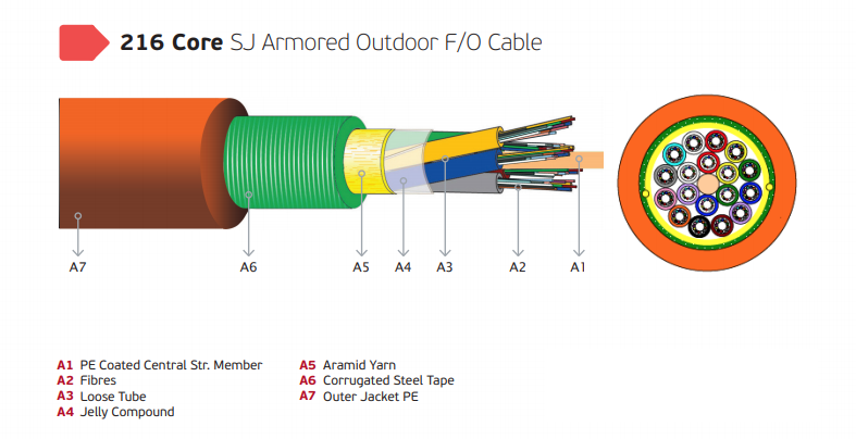
The layers of the cables in the images, from the inside to the outside, are as follows:
|
Layer |
Function |
|
✅ Central Strength Member (A1) |
The FRP or steel support element at the centre of the cable. It provides tensile strength and limits the expansion and contraction of the cable with temperature. |
|
✅ Fibres (A2) |
The fibres that carry the data, made of high-purity SiO₂ glass. |
|
✅ Loose Tube (A3) |
The plastic tube inside which the fibres lie freely. When the cable is under tension or expands with heat, the load is not transferred to the fibre. |
|
✅ Jelly Compound (A4) |
Fills the gaps inside the tube and prevents water from travelling along the cable and reaching the fibre. |
|
✅ Aramid Yarn (A5) |
Carries the tensile force and protects the fibres during installation. |
|
✅ Corrugated Steel Tape (A6) |
The corrugated steel armour that protects against crushing, impact and rodents. |
|
✅ Outer Jacket PE (A7) |
The polyethylene outer jacket, which is resistant to UV light, moisture and chemicals. |
3.3- Multi-Core Fibre (MCF) and Submarine Systems
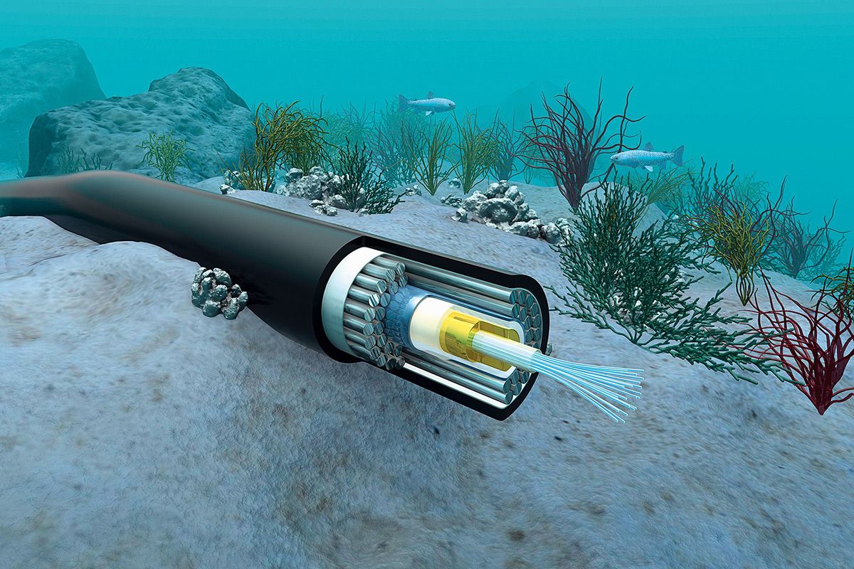
Multi-core fibre (MCF) is a different structure from multi-fibre cables. Here, a single fibre has more than 1 core inside its single cladding. Each core carries a separate optical signal, and the distance between the cores is designed to prevent the signals from interfering with each other (crosstalk). The aim is to multiply the carrying capacity of a single fibre while keeping the same cladding diameter. This approach is called space division multiplexing (SDM).
The area where MCF matters most is submarine systems. These cables are laid under the ocean for thousands of kilometres, and because the cable diameter and the power feed are limited, carrying more capacity in the same cable gives a direct cost advantage. In addition, dense wavelength division multiplexing (DWDM) is applied on each core, which can raise the total bandwidth of a single cable to tens of terabits.
MCF is no longer only a research topic. Sumitomo Electric started mass production of 2-core submarine MCF in 2023. Google and NEC announced in the same year that MCF would be used in the Taiwan-Philippines-U.S. cable system. Meta, NEC and Sumitomo Electric announced the Petal system, which will be about 7,000 km long between the USA and France and will use 48 core pairs with 2-core fibre; the system is planned to enter service in 2029. Even so, most submarine cables still operate with single-core fibre pairs, and the widespread operational use of MCF is at an early stage.
The areas that MCF targets are not limited to submarine systems. Manufacturers also list long-distance, high-capacity terrestrial transmission and links between data centres among the application areas of this technology. In cabling inside enterprise data centres and in campus networks, MCF is not yet a common standard.


4- Multimode Fibre Optic Cable
Fibre optic cables are divided into 2 main groups according to the number of paths (modes) that light can follow inside the core: multimode and singlemode. In multimode fibre, the cladding diameter is 125 µm, the core diameter is 62.5 µm or 50 µm, and transmission takes place at the 850 nm and 1300 nm wavelengths. The wide core allows the light to travel along many different paths. Multimode fibres are divided into 2 types according to their refractive index profile.
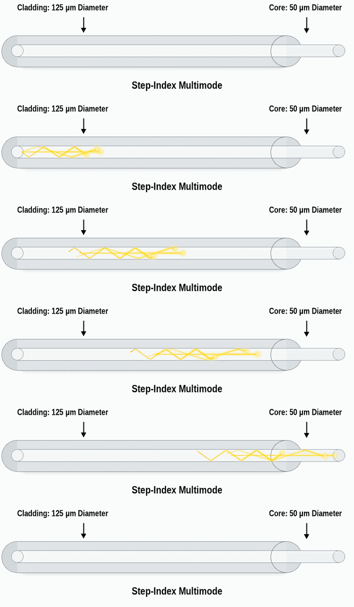
4.1- Step-Index Multimode Fibre
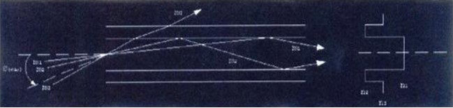
In step-index fibre, the refractive index of the core is the same at every point and drops in a single step at the cladding boundary. When light strikes the boundary between the core and the cladding, it either reflects and stays inside the core or passes into the cladding and is lost, depending on the angle at which it strikes. The key concept here is the critical angle.
The critical angle is measured relative to the normal of the boundary surface (the line perpendicular to the surface). If the light arrives at an angle larger than this angle, that is, at a shallower angle to the surface, it reflects and travels inside the core in a zigzag path. If it arrives at a smaller angle, that is, more perpendicular to the surface, it passes into the cladding and the signal is lost.
To picture this, think of skimming a stone on water. If you throw the stone at a shallow angle to the water, it bounces off the surface and continues. If you throw it steeply, it enters the water and sinks. The light inside the fibre works on the same principle.
|
Type of Strike |
Relative to the Critical Angle |
Result |
|
👉 Shallow strike |
Larger than the critical angle |
The light reflects and continues to travel inside the core |
|
👉 Steep strike |
Smaller than the critical angle |
The light passes into the cladding and the signal is lost |
The range of entry angles that the fibre can accept is defined by the numerical aperture (NA). The NA is calculated from the refractive index difference between the core and the cladding, and it determines the acceptance angle at the end of the fibre. Light that arrives outside this angle cannot meet the critical angle condition inside the core and is lost at the first strike.
✔ Conditions That Cause Light to Escape from the Fibre
In the ideal scenario, the light reflects along the fibre without loss and reaches the far end. In the field, however, some conditions disturb this balance and cause signal loss.
|
Condition |
Effect |
|
The angle of the light source is outside the NA limit |
Part of the light from the LED or laser falls outside the acceptance angle and never couples into the fibre. |
|
Poor connector alignment |
The cores of the 2 fibre ends do not overlap fully, part of the light cannot pass into the opposite core, and insertion loss increases. |
|
Contamination on the fibre end |
Dust and oil scatter and absorb the light. Connector ends must be cleaned and inspected before they are plugged in. |
|
Sharp bending (macrobending) |
At the bend, the angle of incidence at the boundary falls below the critical angle and the light escapes into the cladding. |
|
Pressure, vibration and temperature difference (microbending) |
Load on the cable or contraction caused by temperature creates micro-bends in the core and increases attenuation. |
|
Weak refractive index difference |
If the index difference between the core and the cladding was not formed clearly enough during manufacturing, the light escapes more easily. |
|
Micro-cracks left from manufacturing |
They scatter the light and, over time, can grow with moisture and cause the fibre to break. |
|
Moisture |
In poorly sealed cables, OH ions increase attenuation and start stress corrosion in the glass. |
In the step-index structure, all light rays travel at the same speed, but the rays that zigzag travel a longer path than the rays that go straight along the core axis. For this reason, rays sent at the same moment reach the far end at different times, and the signal pulse spreads. This effect is called modal dispersion, and it is the main factor that limits the bandwidth and distance of step-index multimode fibre.
The multimode fibre standards of Ethernet are based on graded-index fibre with 50 µm and 62.5 µm core diameters, and all of the OM1-OM5 classes used in data networks today have a graded-index structure. I see the step-index structure mostly in plastic optical fibre (POF), large-core industrial short-distance links, and medical and lighting applications.
4.2- Graded-Index Multimode Fibre
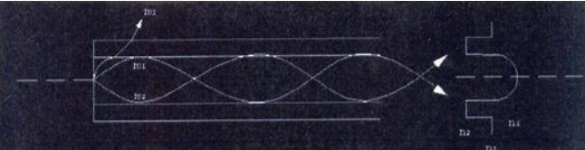
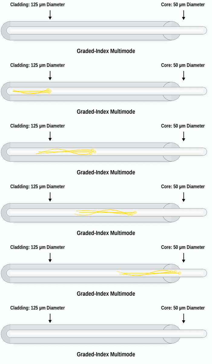
Graded-index multimode fibre was developed to solve the modal dispersion problem. The refractive index of the core is highest at the centre and decreases gradually towards the cladding. Light travels more slowly in the region where the refractive index is high and faster in the region where it is low.
The ray that goes straight along the core axis takes the shortest path, but it travels slowly because it passes through the centre, where the index is highest. The rays that spread towards the edges take a longer path, but they travel faster because they pass through regions where the index is low. As a result, rays that follow different paths reach the far end at almost the same time.
You can picture it like this: 2 vehicles leave at the same time, one on a short but slow city road and the other on a long but fast motorway. If their speeds are set correctly, they reach the destination at the same time. In the graded-index structure, the refractive index profile makes this adjustment.
The graded index does not return the light with sharp reflections. It bends the light back towards the core axis along a curved path that resembles a sine wave. The light is kept inside the core without striking the cladding boundary hard, and the signal pulse spreads much less.
This structure provides stable transmission on links of 10G and above, on switch and server links inside the data centre, and on links within a cabinet and between cabinets. OM3, OM4 and OM5 fibres also have an index profile optimised for laser sources (VCSEL).
📊 Comparison Table
In the table below, I bring together the differences between step-index and graded-index multimode fibres, along with the balance of advantages and disadvantages.
|
Property / Criterion |
Step-Index Multimode Fibre |
Graded-Index Multimode Fibre |
|
Core Structure |
Constant refractive index profile |
Graded refractive index profile that decreases from the centre outwards |
|
Light Path |
Zigzag paths with sharp reflections |
Curved paths that resemble a sine wave |
|
Light Speed Distribution |
All rays at the same speed, the path difference becomes a time difference |
Speed varies with the path, the time difference is compensated |
|
Modal Dispersion |
High |
Low |
|
Bandwidth |
Low |
From 200 MHz·km in OM1 to 4700 MHz·km in OM4 |
|
Usable Distance |
Short-distance applications |
Depends on the standard, for example 300 m on OM3 and 400 m on OM4 for 10GBASE-SR |
|
Application Area |
POF, industrial short-distance, medical and lighting applications |
Data centres, high-speed LANs, in-building backbone |
|
Manufacturing |
Simple and cheap |
The index profile requires precise manufacturing, the cost is higher |
|
Advantages |
Cheap, light is easy to couple because of the wide core |
Low modal dispersion, high speed, standard Ethernet support |
|
Disadvantages |
High modal dispersion, not the structure that the Ethernet fibre standards are based on |
More expensive than step-index, shorter distance than singlemode |
📊 Which Fibre for Which Case?
When choosing between step-index and graded-index, you need to look at the usage scenario, not at the structure of the cable. The table below shows which need each of the 2 structures meets in the field.
|
Criterion / Scope |
Step-Index Multimode Fibre |
Graded-Index Multimode Fibre |
|
When Is It Preferred? |
👉 In non-Ethernet applications that require low speed and very short distance.
👉 When a cheap and easily coupled light source is the priority. |
👉 On every Ethernet-based multimode link.
👉 At speeds of 10G and above, with OM3, OM4 or OM5. |
|
Preferred Cases |
✔ Home and automotive networks with POF
✔ Industrial sensor and control links
✔ Medical devices and lighting
✔ Optical experiment setups for teaching |
✔ Data centre infrastructure of 10G and above
✔ Switch-to-switch backbone
✔ Patch links inside a cabinet
✔ Server-to-switch links
✔ Storage and virtualisation |
4.3- OM1, OM2, OM3, OM4 and OM5 Classes
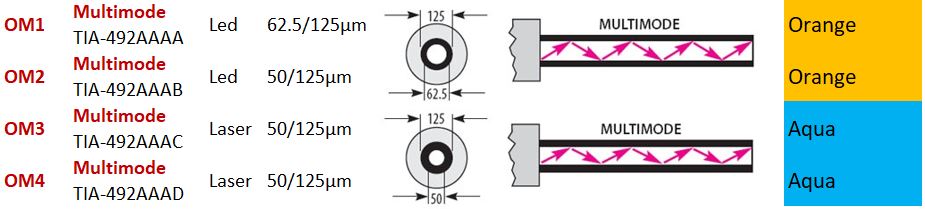
Graded-index multimode fibres are defined by OM (Optical Multimode) classes in the ISO/IEC 11801 and TIA-568 standards. What separates the classes is the core diameter, the light source they are optimised for and the bandwidth. From OM3 onwards, bandwidth is expressed as the effective modal bandwidth (EMB), which is measured for laser sources.
|
Class |
Standard |
Core / Cladding |
Light Source |
Bandwidth |
Jacket Colour |
|
OM1 |
TIA-492AAAA |
62.5 / 125 µm |
LED (legacy); also supports laser-based optics such as 1000BASE-SX |
200 MHz·km (850 nm), 500 MHz·km (1300 nm) |
Orange |
|
OM2 |
TIA-492AAAB |
50 / 125 µm |
LED (legacy); also supports laser-based optics such as 1000BASE-SX |
500 MHz·km (850 nm and 1300 nm) |
Orange |
|
OM3 |
TIA-492AAAC |
50 / 125 µm |
Laser (VCSEL) |
EMB 2000 MHz·km (850 nm) |
Aqua |
|
OM4 |
TIA-492AAAD |
50 / 125 µm |
Laser (VCSEL) |
EMB 4700 MHz·km (850 nm) |
Aqua (Erika Violet is also used in Europe) |
|
OM5 |
TIA-492AAAE |
50 / 125 µm |
Laser, 850-953 nm SWDM |
EMB 4700 MHz·km (850 nm), 2470 MHz·km (953 nm) |
Lime Green |
OM5 was developed for short wavelength division multiplexing (SWDM). It carries several wavelengths between 850 nm and 953 nm on the same fibre, which makes 40G and 100G transmission possible over a single fibre pair without parallel optics.
The jacket colour alone does not prove the fibre class. The class (OM3, OM4, OS2) and the standard printed on the cable must be taken as the reference.
4.4- Multimode Ethernet Standards and Distances
The IEEE 802.3 standards define multimode distances by core diameter and modal bandwidth conditions, not by OM class name. For example, the condition for 100BASE-FX is 50/125 or 62.5/125 µm fibre and a bandwidth of 500 MHz·km at 1300 nm. In the table below, I place these conditions in the columns of the OM classes that meet them. A dash means that the standard is not defined for that fibre.
|
Standard |
Speed |
Wavelength |
OM1 |
OM2 |
OM3 |
OM4 |
OM5 |
100BASE-FX |
100 Mbps |
1300 nm |
2 km |
2 km |
2 km |
2 km |
2 km |
1000BASE-SX |
1 Gbps |
850 nm |
275 m |
550 m |
550 m |
550 m |
550 m |
1000BASE-LX |
1 Gbps |
1310 nm |
550 m (with MCP) |
550 m (with MCP) |
550 m (without MCP) |
550 m (without MCP) |
550 m (without MCP) |
10GBASE-SR |
10 Gbps |
850 nm |
33 m |
82 m |
300 m |
400 m |
400 m |
40GBASE-SR4 |
40 Gbps |
850 nm |
- |
- |
100 m |
150 m |
150 m |
100GBASE-SR10 |
100 Gbps |
850 nm |
- |
- |
100 m |
150 m |
150 m |
100GBASE-SR4 |
100 Gbps |
850 nm |
- |
- |
70 m |
100 m |
100 m |
1000BASE-LX is a standard defined under IEEE 802.3z to operate at 1310 nm over both singlemode and multimode fibre. In multimode fibre, when the laser light is focused exactly on the centre of the core, it can create a delay difference between the modes (differential mode delay). To prevent this on FDDI-grade, OM1 and OM2 fibres, a mode conditioning patch cord (MCP), which launches the laser light offset from the centre of the core, is used at both ends of the link. An MCP is not used on the laser-optimised fibres from OM3 onwards.
On these short links without an MCP, the receiver must be protected from saturation by excessive power, and the measure required for this depends on the optic. According to the Cisco documentation, the conditions for the 3 optics at 1310 nm that can run over multimode are as follows:
|
Optic |
FDDI-grade, OM1 and OM2 |
OM3 and Later |
1000BASE-LX/LH |
MCP required |
MCP is not used. The received power is measured, and if it is above -3 dBm, a 5 dB attenuator for 1310 nm is fitted to the transmitter at both ends. |
10GBASE-LX4 |
MCP required |
MCP is not used. A 5 dB attenuator for 1310 nm is fitted to the transmitter at both ends. |
10GBASE-LRM |
MCP required |
MCP is not used. The received power is measured, and if it is above 0.5 dBm, a 5 dB attenuator for 1310 nm is fitted to the transmitter at both ends. |
The values in the table are based on the Cisco transceiver documentation. If an optic from a different vendor is used, the MCP and attenuator requirement must be verified from that transceiver's own documentation.
40GBASE-SR4, 100GBASE-SR4 and 100GBASE-SR10 use parallel optics. The data is sent over several fibres at the same time, and these links use multi-fibre MPO/MTP connectors instead of a single duplex LC. Today, SR4 is mostly preferred over SR10 in new installations.
Optics must be used with the fibre type they are defined for. Moving between multimode and singlemode is possible only with 1310 nm optics that support both fibre types, such as 1000BASE-LX, 10GBASE-LX4 and 10GBASE-LRM.
5- Singlemode Fibre Optic Cable
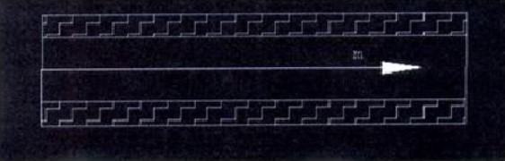
In singlemode fibre, the cladding diameter is again 125 µm, but the core is about 8-9 µm in diameter, and transmission takes place at the 1310 nm and 1550 nm wavelengths. At these wavelengths, the fibre carries only a single fundamental mode. This mode should not be thought of as a single ray that travels along the core axis; the optical field is concentrated inside the core, and part of it extends into the cladding and forms a distribution called the mode field. Because there is no more than 1 mode, the modal dispersion seen in multimode does not occur here.
Dispersion does not end completely in singlemode either. Chromatic dispersion, which comes from different wavelengths travelling at different speeds in glass, and polarisation mode dispersion (PMD), which comes from the speed difference between the 2 polarisation axes of the fibre, become limiting factors, especially at speeds above 10G and over long distances. Fibre attenuation is usually lower in the 1550 nm region than at 1310 nm, but the chosen Ethernet standard and transceiver, not the distance, determine which wavelength a link uses. For example, 10GBASE-ER uses 1550 nm at 40 km, while 40GBASE-ER4 and 100GBASE-ER4 cover the same 40 km with 4 wavelengths in the 1310 nm band.
Transmission in singlemode fibre uses a laser source. The wide light beam of an LED cannot be coupled efficiently into an 8-9 µm core.
Never look into an active fibre end or transceiver port with the naked eye. Laser light at 1310 nm and 1550 nm is invisible and can cause permanent damage to the eye.
5.1- The Difference Between OS1 and OS2
Singlemode cables are defined by OS (Optical Singlemode) categories. OS1 and OS2 are both cable categories, and both nominally use 9/125 µm ITU-T G.652 fibre. The main difference between them is the maximum attenuation limit allowed in cabled form; the limit for OS2 is lower than the limit for OS1. G.652.D fibre, which has the water peak removed (low water peak), is not specific to OS2; the same fibre can be used in cables that meet the OS1 or the OS2 requirements. For this reason, it is not correct to map OS1 exactly to G.652 and OS2 exactly to G.652.D.
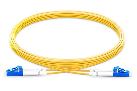
The OS class, the cable structure and the colour are also separate properties. OS2 fibre can be used in loose tube outside plant cables as well as in tight buffer indoor and indoor/outdoor cables. A yellow jacket is the common identification colour for singlemode in indoor cables and patch cords; outside plant and indoor/outdoor OS2 cables are most often manufactured with a black jacket. For this reason, when I choose a cable, I check the fibre class, the cable construction and the print on the cable separately.

|
Property |
OS1 |
OS2 |
|
Fibre Used |
ITU-T G.652 (including G.652.D) |
ITU-T G.652 (commonly G.652.D) |
|
Maximum Cable Attenuation |
A higher limit than OS2 |
0.4 dB/km (1310 nm, 1383 nm and 1550 nm) |
|
Jacket Colour |
Usually yellow in indoor cables and patch cords |
Usually yellow in indoor cables and patch cords, most often black in outside plant and indoor/outdoor cables |
|
Area of Use |
In-building and short campus links |
Links between campuses, metropolitan links and long-distance links |
5.2- Singlemode Ethernet Standards and Distances
The distances in the table below are the longest reaches defined by the relevant standard or vendor. For a link to actually reach this distance, the fibre type specified by the standard, the optical power budget of the transceiver and the permitted channel insertion loss conditions must all be met together. For example, on 40 km class links, spans longer than 30 km are treated as engineered links, and the attenuation of the span must stay below the worst case defined for singlemode fibre. For this reason, on long-distance links, especially on OS1 cables, which have a higher attenuation limit, I verify the real attenuation of the cable in use and the link budget calculation before installation.
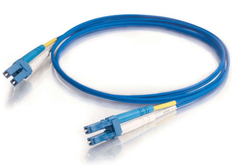
On singlemode links, I also pay attention to the polish type on the connector side: blue connectors indicate UPC polish and green connectors indicate angled APC polish, and the 2 must not be mated with each other.
|
Standard |
Speed |
Wavelength |
Distance |
Defined By |
100BASE-LX10 |
100 Mbps |
1310 nm |
10 km |
IEEE 802.3ah (Clause 58) |
1000BASE-LX |
1 Gbps |
1310 nm |
5 km |
IEEE 802.3z (Clause 38) |
1000BASE-LX10 |
1 Gbps |
1310 nm |
10 km |
IEEE 802.3ah (Clause 59) |
1000BASE-EX |
1 Gbps |
1310 nm |
40 km |
Vendor-defined |
1000BASE-ZX |
1 Gbps |
1550 nm |
70 km |
Vendor-defined |
10GBASE-LR |
10 Gbps |
1310 nm |
10 km |
IEEE |
10GBASE-LX4 |
10 Gbps |
4 wavelengths in the 1310 nm band |
10 km |
IEEE |
10GBASE-ER |
10 Gbps |
1550 nm |
40 km |
IEEE |
10GBASE-ZR |
10 Gbps |
1550 nm |
80 km |
Vendor-defined |
40GBASE-LR4 |
40 Gbps |
4 wavelengths in the 1310 nm band |
10 km |
IEEE |
40GBASE-ER4 |
40 Gbps |
4 wavelengths in the 1310 nm band |
40 km |
IEEE |
100GBASE-LR4 |
100 Gbps |
4 wavelengths in the 1310 nm band |
10 km |
IEEE |
100GBASE-ER4 |
100 Gbps |
4 wavelengths in the 1310 nm band |
40 km |
IEEE |
1000BASE-LX and 1000BASE-LX10 are separate IEEE standards. Standard 1000BASE-LX defines 5 km over singlemode fibre; however, some vendors manufacture 1000BASE-LX compatible LX/LH modules with higher optical quality and give a reach of 10 km over singlemode. This value is part of the module's own specification, not of the standard.
1000BASE-EX, 1000BASE-ZX, 1000BASE-LH and 10GBASE-ZR are vendor definitions, not IEEE standards. The real distance and wavelength must be verified from the datasheet of the transceiver in use.
6- Choosing the Right Fibre Type
Multimode and singlemode fibres are designed for different needs. Multimode fibre, with VCSEL-based short-reach optics, is widely used on links that do not exceed a few hundred metres, such as those in data centres and inside buildings. In new multimode installations, choosing OM3 or higher fibre gives longer distances at 10G and higher speeds, and flexibility for the future. An existing OM1 or OM2 infrastructure does not need to be re-cabled in every case when moving to 10G; 10GBASE-SR works up to 33 m over OM1 and up to 82 m over OM2, and if the link is within these limits, the existing cable can remain in use. In new installations I prefer OM4, or OM5 if SWDM is planned.
Singlemode fibre, with its narrow core and low attenuation, works over distances of many kilometres, and the speed of a fibre installed today can be increased in the future by changing the transceiver. On links between buildings, between campuses and in the outside plant, OS2 is the option that places the fewest restrictions on speed increases over the life of the cable. When choosing a cable, assessing the distance, the target speed and the Ethernet standard that will carry this speed together prevents an expensive job such as re-cabling later.
I hope you find it useful...
Feel free to share your thoughts and questions about this article in the comments below. Every contribution helps the content reach more people and makes for a more useful discussion.